
HP StorageWorks Data Replication Manager HSG80 ACS Version 8.7P Configuration Guide (AA-RPHZF-TE, March 2004)

Troubleshooting
174 Data Replication Manager HSG80 ACS Version 8.7P Configuration Guide
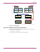
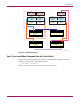
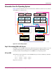
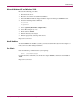
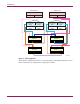
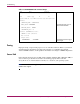
Figure 30 is the cabling diagram with the port connections from the sw14 switch added. The
additional cabling is drawn from information highlighted in Table 15, which shows the
cabling for all four switches:
■ Port 0 of sw14 is cabled to the HBA whose WWID ends in -C9E1.
■ Port 4 of sw14 is cabled to port 1 of the top controller at the same site.
■ Port 5 of sw14 is cabled to port 2 of the top controller at the same site.
■ Port 6 of sw14 is cabled via ISL to port 6 of sw13 (compare with port 6 of sw13 in
Table 13).
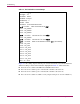
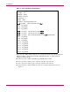
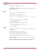
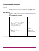
Table 15: Fourth switchShow Command Output
switchName: sw14
switchType: 2.4
switchState: Online
switchRole: Principal
switchDomain: 0
switchId: fffc40
switchWwn: 10:00:00:60:69:00:57:0a
port 0: sw Online F-Port 10:00:00:00:c9:20:c9:e1
port 1: -- No_Module
port 2: -- No_Module
port 3: -- No_Module
port 4: -- sw Online F-Port 50:00:1f:e1:00:07:9d:e3
port 5: -- sw Online F-Port 50:00:1f:e1:00:07:9d:e4
port 6: -- sw Online E-Port 10:00:00:60:69:00:51:5a “sw13” (downstream)
port 7: -- No_Module
port 8: -- No_Module
port 9: -- No_Module
port 10: -- No_Module
port 11: -- No_Module
port 12: -- No_Module
port 13: -- No_Module
port 14: -- No_Module
port 15: -- No_Module