
ISS Technology Update, Volume 7 Number 3 - Newsletter


ISS Technology Update Volume 7, Number 3
10
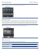
• If a VC-Ethernet Module is installed in an interconnect bay, the only module that can be installed in the adjacent interconnect
bay is another VC-Ethernet Module. A non-Virtual Connect module placed next to a Virtual Connect module will be marked
as incompatible and will not be managed by Virtual Connect.
• If an HP 4Gb VC-Fibre Channel module is installed in an interconnect bay, the only module that can be installed in the
adjacent interconnect bay is another VC-Fibre Channel module.
NOTE
The VC Manager creates bay-specific I/O profiles, assigns unique Media Access Control
(MAC) addresses and World-Wide Names (WWNs) to these profiles, and administers them
locally. The VC Manager will not provision VC-assigned MACs and WWNs to the server
connections that are linked to non-Virtual Connect modules.
Sample Supported Configurations
The Virtual Connect User Guide has several pages of sample configurations supported by Virtual Connect
(
http://h20000.www2.hp.com/bc/docs/support/SupportManual/c00865618/c00865618.pdf). It is not an exhaustive list,
but is meant to show typical supported configurations.
Tables 4-1 and 4-2 give examples of supported configurations for the BladeSystem c7000 Enclosure.
Table 4-1. HP BladeSystem c7000 Enclosure example of a typical supported configuration
Bay Module Bay Module
1 VC-Ethernet 2 VC-Ethernet
3 Other/empty 4 Other/empty
5 VC-Ethernet 6 VC-Ethernet
7 Empty 8 Empty
Table 4-2. HP BladeSystem c7000 Enclosure example of a typical supported configuration
Bay Module Bay Module
1 VC-Ethernet 2 VC-Ethernet
3 VC-Fibre Channel 4 VC-Fibre Channel
5 Other/empty 6 Other/empty
7 Other/empty 8 Other/empty
Tables 4-3 and 4-4 give common examples of supported configurations for the BladeSystem c3000 Enclosure.
Table 4-3. HP BladeSystem c3000 Enclosure example of a typical supported configuration
Bay Module Bay Module
1 VC-Ethernet 2 VC-Ethernet
3 Empty 4 Empty
Table 4-4. HP BladeSystem c3000 Enclosure example of a typical supported configuration
Bay Module Bay Module
1 VC-Ethernet 2 VC-Ethernet
3 VC-Fibre Channel 4 VC-Fibre Channel