
ISS Technology Update, Volume 7 Number 3 - Newsletter


ISS Technology Update Volume 7, Number 3
5
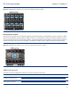
The NonStop signal midplane has eight 200-pin connectors to support eight individual switches, four double bay switches, or a
combination of the two. The eight interconnect bays at the rear of the enclosure accommodate eight single or four redundant
interconnect modules. All interconnect modules plug directly into these interconnect bays. Each HP BladeSystem c-Class
Enclosure requires two interconnect switches or two pass-thru modules, side-by-side, for a fully redundant configuration.
The Onboard Administrator is the terminating point for all interconnect bays. An interconnect module cannot use the connection
to the Onboard Administrator to communicate with another interconnect module. The signal midplane also carries the
management signals from each bay to the Onboard Administrator modules. However, the management signals are completely
isolated from the high-speed server-to-interconnect signals.
Fabric connectivity and port mapping
Because the connections between the device bays and the interconnect bays are hard-wired through the NonStop signal
midplane, the mezzanine cards must be matched to the appropriate type of interconnect module. For example, a Fibre Channel
mezzanine card must be placed in the mezzanine connector that connects to an interconnect bay holding a Fibre Channel
switch. To simplify the installation of the various mezzanine cards and interconnect modules, the Onboard Administrator uses
an “electronic keying” process to detect any mismatch between the mezzanine cards and the interconnect modules.
Interconnect bays 1 and 2 are reserved for Ethernet switches or pass-thru modules supporting server LAN on Motherboard
(LOM) NIC connections to ports on the Ethernet switch or pass-thru module. Supported bays for additional Ethernet switch
modules include unpopulated interconnect bays 3/4, 5/6, or 7/8. Redundant switches must be configured adjacent to one
another in interconnect bays 3/4, 5/6, or 7/8.
Connecting the ports of embedded devices to the interconnect bays in the HP BladeSystem c7000 Enclosure is relatively simple.
For port mapping, it does not matter in which bay a server blade is installed. The mezzanine connectors always connect to the
same interconnect bays.
Port mapping differs slightly between full-height and half-height server blades because full-height blades support additional
mezzanine cards. HP has simplified mapping mezzanine ports to switch ports by providing intelligent management tools such
as the Onboard Administrator and HP Systems Insight Manager software. The HP BladeSystem Onboard Administrator User
Guide provides specific port mapping details:
http://h20000.www2.hp.com/bc/docs/support/SupportManual/c00705292/c00705292.pdf.
c7000 bay-to-bay crosslinks
Four-trace SerDes signals between adjacent bays in the c7000 midplane permit bay-to-bay communications. Pairs of single-
wide interconnect modules installed in adjacent horizontal bays provide redundant connectivity for dual-port interfaces in each
device bay. Adjacent interconnect modules also have high-speed cross-connect capability through the enclosure’s NonStop
signal midplane. For double-wide interconnects such as DDR Infiniband, two modules are installed in c7000 interconnect bays
5 and 7 to provide redundant high bandwidth connectivity.
Device bay crosslinks
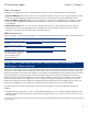
Device bay crosslinks are wired between adjacent horizontal device bay pairs as indicated by the arrows in Figure 2-3. For
half-height server blades, these signals are used for four-lane PCIe connection to a partner device such as a tape blade or PCI
expansion blade. For full-height server blades, these signals are used for PCIe connection to a partner device in the lower
adjacent bay and require a PCIe pass-thru mezzanine card installed in mezzanine connector 3. The Onboard Administrator
disables the device bay crosslinks in instances where they cannot be used, for example between two server blades residing in
adjacent device bays.