
Installing and Administering HP EISA FDDI/9000 and HP HSC FDDI/9000


46 Chapter 3
Installing the HP HSC FDDI/9000 Adapter
Installing the Adapter
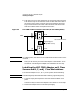
8. Push the Core I/O or HSC Expansion I/O card firmly back into place.
Push down firmly on the extractor levers on both ends of the card to
secure the card in place. Screw the two slot screws back into place.
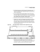
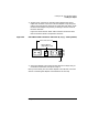
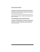
Figure 3-3 shows the HSC FDDI cable connectors and LEDs. Note
that the numbers shown correspond to the LEDs.
Figure 3-3 HSC FDDI Cable Connectors and LEDs (K and T-600 Systems)
NOTE On T-600 systems, the LEDs are not visible when the HSC FDDI card is
installed.
Next you will attach your HSC FDDI adapter to the network. Go to
the section “Connecting the Adapter to the Network” for this step.
Installing the HSC FDDI Adapter on D Class
Servers and B, C, and J Class Workstations
To install the adapter in B, C, D, or J class systems, do the following:
NOTE The following steps should be done while wearing a grounding strap.
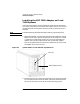
1. Locate an empty HSC expansion slot and remove the blank cover
plate.
Save the screw(s) to secure the adapter to the chassis in a later step.
2. Remove the adapter from its antistatic packaging.
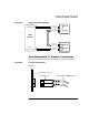
LEDs
SC Connector Ports
Optical Bypass
(6-pin DIN socket)
(1)
(2)
(3)
(4)
(1)
Port B
Port A