
Installing and Administering HP EISA FDDI/9000 and HP HSC FDDI/9000


Chapter 3 47
Installing the HP HSC FDDI/9000 Adapter
Installing the Adapter
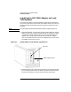
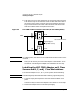
3. Align the HSC connector on the HSC FDDI adapter with the I/O
Expansion connector in the slot. Press the adapter firmly into place,
making sure that the two connectors are flush with each other. Screw
the HSC FDDI adapter into place by screwing in the two screws on
the front of the slot.
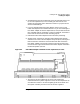
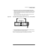
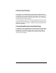
Figure 3-4 shows the HSC FDDI cable connectors and LEDs. Note
that the numbers shown correspond to the LEDs.
Figure 3-4 HSC FDDI Cable Connectors and LEDs (B, C, D, J Class Systems)
4. Secure the adapter to the system chassis with the screw(s) that you
removed from the blank cover plate in step 1.
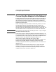
Next you will attach your HSC FDDI adapter to the network. Go to the
section “Connecting the Adapter to the Network” for this step.
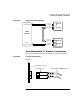
LEDs
SC Connector Ports
Optical Bypass
(6-pin DIN socket)
(4)
(3)
(2)
(1)
Port B
Port A