
PCI MUX Cabling Solutions
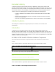
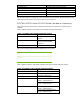
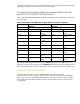
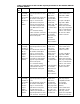
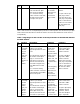
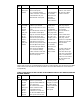
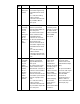
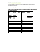


Table 11 provides pin diagrams for converting A6748A/A6749A RS-232 DB25 Serial Port to
AD278A/AD279A RS-232 RJ45 Serial Port.
Table 11: Converting A6748A/A6749A RS-232 DB25 Serial Port to
AD278A/AD279A RS-232 RJ45 Serial Port
DB25 Female
Port Pin
Number
(A6748A/
A6749A
Solution)
Converter -
DB25 Male
Port Pin
Number
(A6748A/
A6749A
Solution)
RJ45 Pin
Number
(AD278A/
AD279A
Solution)
RS 232 Signal RS 232 Signal
Description
Pin # 2 TXD Transmitted Data Pin # 5
Pin # 3 RXD Received Data Pin # 6
Pin # 4 RTS Request to Send Pin # 3
Pin # 5 CTS Clear to Send Pin # 8
Pin # 6 DSR Data Set Ready Pin # 2
Pin # 7 SG Signal Ground Pin # 7
Pin # 8 DCD Data Carrier
Detect
Pin # 10
Pin # 20 DTR Data Terminal
Ready
Pin # 9
Pin # 22 RI Ring Indicator Pin # 1
Summary
This paper discusses solutions for different cabling issues that are caused by RS-232 serial port pin-
layout and port interface differences between the A6748A/A6749A serial PCI MUX solution and the
AD278A/AD279A serial PCI MUX solution.
Glossary
Port Modules: Port modules are extended equipments that are used with 64-port serial MUX solution
to provide RS-232 serial ports. One port module can be connected to PCI MUX 64-port adapter and
others can be extended from the first port module.
Related Information
For more information about the A6748A/A6749A and AD278A/AD279A serial PCI MUX solutions,
see the Multiplexers Documentation website at:
http://www.docs.hp.com/en/netcom.html#Multiplexers