HP-UX 11i v3 Crash Dump Improvements January, 2007 Executive Summary ......................................................................................................................... 2 1 Overview of HP-UX 11i v3 Dump Improvements............................................................................ 2 2 Terms and Definitions ............................................................................................................... 3 3 Performance Improvements..........................
Executive Summary Crash dump, the ability to write (dump) a copy of system memory onto disk in the event of a catastrophic system failure, is critical for system problem analysis and resolution. The Crash Dump utility has been enhanced in HP-UX 11i v3 to significantly increase performance and scalability, and to improve the availability and manageability of the dump configuration.
2 Terms and Definitions General Terms: HBA Host Bus Adapter. E.g., an I/O card with one or more ports on it for attachment to Fibre Channel, parallel SCSI, or other mass storage connectivity to a dump device. Target A storage device attachment to a mass storage interconnect such as Fibre Channel or SCSI. LUN An end device in a mass storage interconnect. A dump device in this paper. Dump Related Terms: Dump unit A thread of execution during dump.
3.1 Requirements 3.1.1 Platform support In the initial release of HP-UX 11i v3 only HP Integrity servers will support parallel dump. Enabling parallel dump on HP 9000 servers will not be allowed. 3.1.2 Driver Capabilities I/O support during dump is provided via dump drivers, and each configured dump driver reports its parallelism capabilities to the dump infrastructure.
o Devices controlled by concurrent dump drivers: each “concurrent device” can be accessed in parallel. Each can therefore be assigned to a separate dump unit, even if configured through a single HBA port. o Logical volumes configured as dump devices (e.g., in an LVM environment): all logical volumes which reside on the same physical device (LUN) are assigned to the same dump unit.
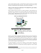
Figure 2 shows the CPUs used in three dump units. Uncompressed dump uses 3 of the 16 CPUs, while compressed dump uses 15 of the 16 available CPUs. Figure 2 – CPU Usage in Three Dump Units D1 D2 D1 D2 D3 D3 Compressed Dump Uncompressed Dump = available CPUs = CPUs assigned to dump units = dump device(s) assigned to dump units 3.2.2 Devices and Dump Units Figure 3 illustrates the relationship between devices controlled by legacy dump drivers (“legacy dump devices”) and dump units.
Figures 4 and 5 illustrate the relationship between devices controlled by reentrant dump drivers (“reentrant dump devices”) and dump units. Multiple reentrant devices can be accessed in parallel if they are on separate HBA ports. In Figure 4 the three reentrant devices are only accessible via a single HBA port and thus get assigned to a single dump unit. In Figure 5 the reentrant devices are accessible via three different HBA ports, allowing three dump units to be created.
Figures 8 and 9 combine elements of each of the above examples to illustrate more complex sets of devices and dump units. Figure 8 shows an uncompressed example with 2 legacy devices, 4 reentrant devices through 3 HBA ports, and 2 concurrent devices. The two legacy devices are assigned to one dump unit; the two concurrent devices each get assigned to an additional dump unit; and the four reentrant devices are assigned to three additional dump units (one for each of their 3 HBA ports).
chosen, with the following exception: concurrent HBAs will always be selected over reentrant HBAs once the available ports have all been used. This exception is due to the fact that having more than one reentrant device on the same HBA port will not increase parallelism. Offline or disabled paths are not included in the automatic HBA selection. See Section 5, ”Availability and Manageability Improvements”, for information regarding automatic reconfiguration across path offline events.
HBA ports. This situation is illustrated in Figure 12, in which reordering or disabling produces a dump configuration in which both HBA ports are used. Configuration Ordering in HBA Selection Figure 11 – Dev2 then Dev1 Figure 12 – Dev1 then Dev2 D1 hba1 Dev1 hba2 D1 D2 hba1 hba2 Dev1 Dev2 Configuration of Dev2 before Dev 1 can result in only 1 of the 2 HBA ports being used.
3.4.1 Hardware overlap across dump units Performance tends to scale better when the hardware overlap (sharing of components such as HBAs, links, targets) between paths to devices in different dump units is minimized. For example, performance will generally be better when dump devices for separate dump units are configured through separate target ports. Dumps generate large sequential writes which will compete for bandwidth on the link and in the target controller.
gated by the dump unit which takes the longest time to complete the dump of its memory area, the imbalances inherent in compressed dump can reduce the scalability of the parallelism. For example, on a system with 3 dump units with equal sizes of memory to be dumped and equal I/O rates to the disk, the uncompressed dump time for each dump unit would be equal. I.e., without compression if one dump unit takes 30 minutes to complete the overall dump time will be 30 minutes plus dump startup and completion time.
3.4.5 Recommended procedure to configure parallel dump for performance The following outlines a recommended procedure to configure parallel dump for performance: 1. Identify the available devices and HBA ports for dump. 2. Calculate the maximum CPU parallelism for both compressed and uncompressed dump. 3. Calculate the maximum Device parallelism. 4. Calculate the overall dump parallelism based on steps 2 and 3 for compressed and uncompressed dump. See the formulas at the end of section 3.1. 5.
4 Configuration Improvements 4.1 Persistent Marking of Dump Devices In HP-UX 11iv2 there are several mechanisms available for persistent marking of dump devices (causing the dump configuration to persist across reboots). The mechanism that can be used depends on whether the dump device is an LVM or VxVM volume, or a raw device, and includes the following: • /stand/system: • lvlnboot: • vxvmboot: dump devices can be specified in the /stand/system file as described in the system(4) man page.
and a new device file name (known as a “persistent” device special file) introduced in HP-UX 11i v3 that corresponds to the LUN itself. If a dump device is configured using a legacy device file name the dump infrastructure will convert it to the new LUN device file and then choose a lun path as discussed in Section 3.3. See the man page intro(7) and the HP-UX 11i v3 Mass Storage Device Naming White Paper for general information and details regarding the HP-UX 11i v3 device file formats. 4.
5 Availability and Manageability Improvements Many of the availability and manageability improvements make use of the native multi-pathing provided in HP-UX 11i v3. The native multi-pathing automatically correlates the paths to a LUN and notifies the dump subsystem of path offline and device offline events and other hardware events so that the dump configuration can be automatically adjusted as needed. The events and reconfiguration are available at run time, not at dump time.6 5.
# crashconf -v Crash dump configuration has been changed since boot.
5.5 Expansion/contraction of dump device The HP-UX I/O subsystem in HP-UX 11i v3 supports online expansion and contraction of the size of luns. The dump subsystem will get event notification when the size of a dump device (full raw disk) expands or contracts. Dump will then dynamically update the internal data structures and at dump time the expanded/contracted device size will be used. 5.6 Additional features 5.6.