HP VAN SDN Controller Administrator Guide Abstract This guide is intended for network administrators and support personnel involved in configuring and managing HP VAN SDN (Virtual Area Network Software-Defined Networking) Controller installations. The information in this guide is subject to change without notice. HP Part Number: 5998-4919 Release 2.
© Copyright 2013-2014 Hewlett-Packard Development Company, L.P. Confidential computer software. Valid license from HP required for possession, use or copying. Consistent with FAR 12.211 and 12.212, Commercial Computer Software, Computer Software Documentation, and Technical Data for Commercial Items are licensed to the U.S. Government under vendor’s standard commercial license. The information contained herein is subject to change without notice.
Contents 1 Introduction.................................................................................................................. 6 Supported Switches and OpenFlow Compatibility .......................................................................... 7 2 SDN Controller Console ................................................................................................ 8 Start the SDN Graphical User Interface ...................................................................................
3 SDN Controller Authentication ..................................................................................... 43 HP VAN SDN Controller Security Guidelines ............................................................................... 43 SDN Controller Authentication ................................................................................................... 43 Creating SDN Controller Keystore and Truststore .........................................................................
6 Backup/Restore .......................................................................................................... 67 Overview ................................................................................................................................ 67 Back-Up a Controller ................................................................................................................. 67 Backup Operation ........................................................................................
1 Introduction This document describes the configuration and management of the HP VAN Controller in standalone and team modes. The HP VAN SDN Controller is a Java-based OpenFlow controller enabling SDN solutions such as network controllers for the data center, public cloud, private cloud, and campus edge networks. This includes providing an open platform for developing experimental and special-purpose network control protocols using a built-in OpenFlow controller.
The HP VAN SDN Controller is an extensible platform supporting native applications (sometimes referred to as modules) and external applications. Native applications are authored in Java or a byte-code compatible language and are deployed on the controller as collections of OSGi bundles. Native applications use the Java services exported and advertised by the controller platform and by other applications.
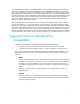
2 SDN Controller Console Start the SDN Graphical User Interface 1. Use the Google Chrome browser to access the controller's GUI at the controller IP address: https://:8443/sdn/ui For example: https://127.0.0.1:8443/sdn/ui 2. Enter user name and password credentials, then click Login. The default user name is "sdn". The default password is "skyline".
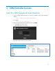
SDN User Window Features To display the SDN User Window, click on console: in the upper right corner of the controller Figure 2 Click to View the SDN User Window Figure 3 The SDN User Window SDN Community is a link to the Software Defined Networking community website within the HP Enterprise Business Community.
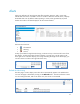
Alerts Alerts give notification of internal events that affect controller operation, and in some cases indicate that some action is needed to correct a condition. When the controller starts, it displays the Global Alerts view by default. When operating in a team, alerts generated by any team member are visible in the Alerts display for all active team members.
Change the Display and Alert Listing Order In the default display (Figure 5, on page 10), alerts are displayed in descending order from newest to oldest, based on the alert date and time. You can change the display order in any of the following ways, by clicking on the appropriate column heading: Severity: Groups alerts by alert level; to , or the reverse. Date/Time: Oldest to newest (the default), or the reverse.
Figure 8 Example of the Alert Popup Window Acknowledging an alert in either the Global Alerts view or in the alert popup window decrements the popup counter, removes the alert from the popup window, and causes the alert to be greyed out in the Global Alerts view. Unacknowledging an alert in the Global Alerts view restores the alert to the popup window. The dashboard Alert notification counter appears in all controller GUI windows.
Figure 9 Select the Alert Manager Configuration Component 3. Click on Modify. Figure 10 View the Alert Component Policy 4. Change the Alert Age-Out policy by changing the Value settings for the Key fields. Figure 11 Alert Age-Out Policy Values 5. Set the new policy by clicking on Apply in the lower right corner of the "Modify Configuration" window.
Application Manager Figure 12 Application Manager with Network Services The Application Manager supports default and add-on network services (APIs), and enables installing, starting, stopping, and uninstalling managed applications. The default API set includes: Path Daemon Node Manager Path Diagnostics Topology Manager Topology Viewer Link Manager Using the Application Manager Note: Most of the Application Manager actions can also be performed using the REST API.
Table 1 Mandatory and Optional Table Attributes Mandatory Attributes* Optional Attributes App_id Description App_name Vendor Version Built_In Support_team Licensing-related *Without these attributes the application deployment will fail. It must contain at least one bundle or a par file. It can contain a plan file which will contain information regarding the bundles in the application. Application Criteria Application components must be valid OSGi artifacts.
Figure 13 OSGi Artifacts (Plans, Bundles, and Pars) Associated with Individual Applications Table 3 Application Content Plan An XML file describing the collection of all bundles associated with the application. Bundles The Jars files (containing the business logic) and the manifest file, which describes the bundle. Pars An archive of all the bundles. (All bundles are managed as a single unit.
4. Click Deploy to deploy and activate the application. The new application then appears by name in the Applications list as "ACTIVE". (To use a cURL command for this procedure, see cURL Commands on page 77.) Notes The Start button is enabled only when an application in the RESOLVED (stopped) or STAGED state is selected. To Stop and Re-Start an Application This procedure temporarily stops an active application from servicing requests, but retains the application on the system.
To Replace an Application This procedure replaces an existing application with either a new version of the same application, or replaces one application type with another, different application type. Note: To replace an application with the same or another version of the same application, you must first remove the current version from the controller. 1. In the Application window, select the application you want to replace. 2. Click on Uninstall to display the Uninstall Application window. 3.
Summary of Built-In Network Services Application TopologyViewer Operation Creates and updates a network graph for visualizing the network the controller discovers. The Topology Viewer uses the services of the Topology Manager and Link Manager. TopologyManager Topology Manager computes the broadcast tree to avoid loops and broadcast storms. On a given switch it also provides the following: Provides a list of discovered ports on a given switch.
10.250.100.2 00:af:cd:12:10:20 110 10.250.100.3 00:af:cd:12:10:02 120 The Node Manager uses the services of the Topology Manager application. Note End hosts connected to non-OpenFlow switches within the network (hybrid network) will not be discovered in a reliable manner Path Daemon Path Daemon is a “proof of concept” network service application built on top of the SDN controller. Path Daemon is responsible for pushing end-to-end flows for all ARP and IPv4 flow misses that arrive at the controller.
configured for the impacted port, thereby causing the packet-ins to again come to the controller.
construct end-to-end paths. Deciphering port state changes. Generates link events to notify interested listeners. Identifies “multi-hop” links between disconnected segments of the control domain. Providing information used by applications to reconfigure flows when a link goes down. To avoid sending LLDP discover packet on certain ports such as an edge port, LinkManager maintains a special list of ports identified as "Suppressed LLDP Ports".
Figure 14 Path Daemon Flowchart Start Flow miss arrives Gets Packet-In for a connected device Register for IPv4 and ARP packet-in types at Director level. Drop packet-in no Is it a broadcast or a multicast packet? Yes Does Topology Service permit flood ? Yes Flood no Are the source and destination end hosts available with Node Service. no Yes Are source and dest end hosts connected to same switch through different interfaces.
Using the Application Manager in a Teamed Environment Using the Application Manager in a teamed environment is similar to the usage in a standalone controller environment. In a teamed environment, an operation performed on any of the controllers is propagated to all the other controllers in the team. Thus, loading a new application on any one controller propagates the application to all other controllers in the team.
Each key includes the current value, or setting, the default setting, and a brief description. Where applicable, the range of suggested settings is also included. For example, the AlertManager component includes the three keys shown below: Figure 16 Example of Configuration Component View View or modify a Component Configuration 1. For a given component, click on the bullet adjacent to the component name to display the Key list and configuration for that component. 2.
Configuration Component Summaries com.hp.sdn.adm.alert.impl.AlertManager Controls the quantity of alert data present on the system by periodically checking for alert data that needs to be aged-out based on the configured age-out policy. com.hp.sdn.adm.auditlog.impl.AuditLogManager Controls the quantity of audit log data present on the system by periodically checking for audit log data that needs to be aged-out based on the configured age-out policy. com.hp.sdn.adm.auth.impl.
com.hp.sdn.ctl.path.impl.PathDaemon Provides parameters used by the path daemon to perform Layer-2 forwarding. com.hp.sdn.misc.AdminRestComponent Provides parameters for internal communication between SDN components and the SDN controller’s Admin REST API. com.hp.sdn.misc.ServiceRestComponent Provides parameters for internal communication between SDN components and the SDN controller North Bound REST API. com.hp.sdn.rs.RestPerfProvider Provides the ability to expose performance metrics for the REST API.
Figure 17 Selecting the Audit Log Audit Log data fields include the following: • User: A string representing the user that performed the operation that triggered the log entry • Occurred: A time stamp (in UTC format) marking when the controller created the audit log entry. • Activity: A string describing the type of activity that triggered the log entry. • Data: A string description providing detail about the audit log entry.
Manage the Audit Log Display In the default configuration, the log page contains up to 100 entries. Using the listing capacity options in the lower right corner of the display, you can reset the listing to a capacity of 10 or 20 entries, or to Auto, (which puts all existing log entries into a continuous listing). The paging information in the lower left corner of the display indicates which page of the log is visible and how many pages of Audit Log entries currently exist.
Setting Audit Log Policy An audit log entry may not be modified or selectively deleted. Entries are removed only as a result of the default age-out policy or a modified policy configured by the administrator. Audit Log data is maintained either by the default policy or by an Administrator-directed policy. Table 4 Audit Log Policy Options Operation Default Range Configuration Key Record Retention 365 Days 31 - 1825 Days trim.auditlog.
Archiving Audit Log Data Outside of the Controller To archive the Audit Log data beyond the age-out policy, use the REST API to export the Audit Log data out of the controller prior to its age-out date. Exporting Audit Log data does not remove it from persistent storage. Support Logs The Support Logs function automatically maintains an internal record of events of interest from the operations of an active SDN controller.
Configure the Support Log for Queue Size The default queue size is 100 lines. To configure a different queue size, change the value for the max.display.rows key in the adm.log.impl.LogManager Configurations component. 1. Click on Configurations. 2. Click on the com.hp.sdn.adm.log.impl.LogManager component. Figure 21 Configuring the Log Queue Size 3. Click on Modify. 4. Click on the Value field and type in the queue size you want. Figure 22 Entering the Queue Size 5.
Log Message Levels Log message levels include the following: ERROR WARN INFO DEBUG TRACE In the default configuration, the ERROR, WARN, and INFO levels are recorded in the Support Logs. DEBUG and TRACE are verbose logging that are used in troubleshooting situations that may involve support engineering. The logging level for a given component that is writing to the support log can be dynamically changed using the Virgo Administrator console.
2. At this point either resume interaction with the controller, or click on the dropdown arrow and take one of the indicated actions in the dropdown menu: o Open a window showing the new log zip file. o Set the default operation to always open the directory containing the log zip file. o Show the log zip file in the default directory for receiving downloads. Note The actions resulting from these choices are not managed by the controller but are a function of the operating system in use.
Figure 26 Example of Selecting an OpenFlow Device by Its Data Path ID Summary View This view includes the following related to the selected device: Device identification (Data Path ID) and IP address TCP port on the device Negotiated OpenFlow version (latest OpenFlow version common to both the controller and the switch) OpenFlow table and buffer information OpenFlow capabilities on the device Figure 27 Result of Selecting the Summary View 35
Ports View This view includes information on the ports used for OpenFlow traffic on the selected device. Figure 28 Example of the Ports View for a Specific OpenFlow Device Flows View This view includes the current flows on the selected OpenFlow device. For a given flow, traffic meeting the requirements specified in the "Matches" field is directed as specified in the corresponding "Actions/Instructions" field.
OpenFlow Topology The Topology viewer displays a topology of discovered switches and end nodes. The viewer creates and updates a graph of the network, and computes the broadcast tree to avoid loops and broadcast storms. The shortest path is computed using Dijkstra’s graph search algorithm. The viewer: • • • • • Displays a topology of discovered switches and end nodes. Identifies the ports discovered on a given switch.
Figure 31 Example of Topology View with Switch and End-Nodes Configure the Topology Display The Topology display includes the switches and end-nodes in the controller domain. End nodes can be labelled with one of the following: No Label (default) IP Address MAC Address For example: Figure 32 Example of End-Node Labelling Switches are always labelled with their MAC address. You can also: Add port labels to the links between switches and between switches and end nodes.
"Collapse" the topology display to show only the number of end nodes connected to each switch, instead of showing all end nodes (the default) which can present a cluttered display where a large number of end nodes are connected to the OpenFlow switches.
Figure 35 Finding the Shortest Path Between Two Nodes 40
Identify Flow Details and Flow Options Select Shortest Path and click on Follow Flow. The Switch Details window appears and displays the flow details and the Abstract Packet window for shortest path for packets moving between the Source-Destination node pair.
OpenFlow Trace This feature provides a trouble-shooting tool for observing (for a very brief period – 10 seconds by default) the OpenFlow interactions captured in messages between the controller and the network. Included are Open Flow messages received by the controller from the OpenFlow devices it manages, and all messages sent from the controller to the devices (both the messages received and the messages sent).
3 SDN Controller Authentication HP VAN SDN Controller Security Guidelines The HP VAN SDN controller communicates with different components, both internal and external to the controller, via secure channels. This section documents these channels, their defaults, and how to configure them in a deployment environment. SDN Controller Authentication The SDN controller identifies itself via Public-Key Infrastructure (PKI) for its communication with external subsystems and other controllers.
Send the sdn-server.csr to a CA to be signed. The CA will authenticate you and return a signed certificate and its CA certificate chain. We assume the signed certificate from the CA is named signed.cer and the CA's certificate is root.cer. If root.cer is from your own internal CA, then you need to import root.cer into your browser as an authority. 6. First, import the signed root certificate into your keystores: keytool -importcert -trustcacerts -keystore keystore -file root.
4. Repeat for the other two components. Figure 40 Components that Reference Controller Keystore and Truststore The values for keystore and keystore.password contain the keystore location and encrypted keystore password respectively. The values for truststore and truststore.password contain the truststore location and encrypted truststore password respectively. Configuration Encryption Sensitive information such as tokens and passwords are stored encrypted on the SDN controller.
Openflow Controller TLS The Openflow controller component relies on PKI to establish mutual trust (2-way SSL) between itself and the Openflow switches that it manages. It is recommended that the Openflow keystore and truststore used for Openflow switch communication be separate from the SDN controller’s keystore and truststore used for north-bound communication.
REST Authentication The SDN controller relies on token-based authentication to authenticate its REST APIs. In other words, all REST APIs except the /auth and /rsdoc APIs require an authentication token embedded in an “X-Auth-Token” header to be included with each REST request. The /auth API allows you to obtain a token, while the /rsdoc API provides live REST API documentation information about the controller’s REST API. The next section describes how to obtain a token from the /auth API.
{ "record": { "domainId": "62e312edff47413fad7e1d7fa6ac7bc7", "domainName": "sdn", "expiration": 1377917359000, "expirationDate": "2013-08-30 19-49-19 -0700", "token": "54a6f80a9ae243db89bfa05de4ced51d", "userId": "bca3dea8a28b457e99e899ae16b79634", "userName": "sdn" } } CAUTION Please guard this token information, as it can be used as an API key to gain access to your SDN controller REST APIs.
Controller Code Verification All controller code is signed by HP. Validating the certificate via jarsigner should return an HP X.509 certificate similar to the following: X.509, CN=Hewlett-Packard, OU=HPGlobal, OU=Digital ID Class 3 - Java Object Signing, O=Hewlett-Packard, L=Andover, ST=Massachusetts, C=US [certificate is valid from 11/14/12 4:00 PM to 11/15/14 3:59 PM] X.509, CN=VeriSign Class 3 Code Signing 2010 CA, OU=Terms of use at https://www.verisign.
Running the Controller Without Jar-Signing Validation The SDN controller enforces jar-signing validation by default. For an experimental/development environment where unsigned applications need to be deployed, jar-signing validation can be turned off altogether: 1. Stop the SDN controller: sudo service sdnc stop 2. Modify the /opt/sdn/virgo/bin/dmk.
Revoking trust via CRL For the controller’s REST API, a CRL (Certificate Revocation List) may also be specified to allow blacklisting of certain clients. This is done by modifying the /opt/sdn/virgo/configuration/tomcat-server.xml file to include the CRL file location in the SSL connector: PAGE 52Virgo Admin UI Access The Virgo admin UI is configured to only be accessible via localhost. Access to this UI can be made via http://localhost:8080/admin. This should not be used under normal circumstances, but can be useful for debugging purposes. To change the credentials of this console, get root console access to the machine(s) running the HP VAN SDN Controller and edit the following file: /opt/sdn/virgo/configuration/org.eclipse.virgo.kernel.users.
Security Practices Recommended Changes Before entering commands that require a password in the command line, enter a space before the command to prevent saving the command into your .bash_history. Change the default SDN Controller’s keystore and truststore passwords. Change the default SDN Controller’s jar-signing truststore password. Change the default SDN Controller’s service token. Change Keystone’s default admin token.
4 Team Configuration Standalone controller operation provides management for the OpenFlow switches in a network. However, it does not provide high availability (HA), with the result that a controller failure leaves the network in an unmanaged state. Configuring a team of controllers and a corresponding controller region creates a high availability network with failover capability, resulting in a continuously managed network in the event that a controller in the team goes down.
Configuring a Controller Team Configuration Prerequisites 1. Install and start three standalone HP VAN SDN controllers in the network. (See the latest HP VAN SDN Controller Installation Guide.) 2. Optional: To improve security, you can change the username and password from the default settings on each of the standalone controllers in step 1. 3. Select any one of the controllers to use for configuring the team. 4. On the selected controller, acquire an Authentication Token.
5. Determine the team configuration parameters: Parameter Value Team Name Alphanumeric character string. Spaces not allowed. Team IP Address The team IP address is different from the individual controller IP addresses. It is used as a virtual address for connecting to the team manager. Member Name Alphanumeric character string. Spaces not allowed. Member IP Address The unique IP address assigned to each controller. Member Priorities Unique numeric value.
Configuration Example This example shows a team of controllers configured with the following team member values: Team Name Team IP Address Member Names Member IP Addresses Member Priority Test_Team 192.0.2.100 Athos 192.0.2.119 10 Porthos 192.0.2.125 20 Aramis 192.0.2.127 30 Domain: sdn (the default domain name) Username: myname Password: mypass Note It is not mandatory that the team IP address be in the same subnet as the member IP addresses.
Display Team Configuration 1. Acquire an authentication token for the team master. (See step 4 on page 55.) 2. Using the token acquired in the preceding step, execute this cURL command to display the team configuration: curl --noproxy --header "X-Auth-Token: " --fail -ksSfL --request GET --url https://:8443/sdn/v2.0/team For example: curl --noproxy 192.0.2.100 --header "X-Auth-Token: " --fail -ksSfL --request GET --url https://192.0.2.119:8443/sdn/v2.
Disband a Team Disbanding a team returns the teamed controllers to standalone operation. Note Before disbanding a team, delete the region configuration for that team. See "Delete a Region" on page 66. 1. Acquire an authentication token for the team master. (See step 4 on page 55.) 2. Using the token acquired in the preceding step, execute this cURL command to disband the team: curl --noproxy --header "X-Auth-Token:" --fail -ksSfL --request DELETE --url https://:8443/sdn/v2.
Controller Fault Tolerance The threshold for controller fault tolerance is 2n+1, where n is the number of failed controllers allowed in an active team. HP VAN SDN Controller teaming supports a team of three controllers. In a team of three controllers, n = 1; one controller in a team of three can fail without suspending team operation.
controller to disband a team. TeamingService not found. Team master election has been triggered while the teaming service is still coming up. Unable to form a quorum. Team configuration has failed on a majority of systems. E.g. a team of three systems has experienced failures on two systems Unprogramming team alias < ip-address > failed.
5 Region Configuration Overview This chapter describes the configuration needed to support High Availability (HA) for HP VAN SDN controllers to OpenFlow switches. This is done by creating region configurations in the controllers using the REST APIs provided by the Role Orchestration Service (ROS). Putting the region configurations in place in a controller team ensures seamless failover and failback among the configured controllers for the specified network devices in a region.
operation in which the master role is restored to the configured master as defined in the region definition. The next section provides details about the various REST operations that can be used to create, update, and delete region configurations. Note Examples of cURL commands in this guide use the "--noproxy" option, which is appropriate where execution of cURL commands does not need a proxy to access controllers.
} ], \"devices\": [ { \"ip\": \"10.250.100.20\" }, { \"ip\": \"10.250.100.21\" } ] } }" Note that a region can have only one master and one or more slave controller(s). Get the Region UID The region ID is required for updating, refreshing, or deleting a region. The cURL command to use for acquiring a region is: curl --noproxy --header "X-Auth-Token:" --header "ContentType:application/json" --fail -ksS --request GET --url https://:8443/sdn/v2.
Update a Region You can update an existing region with more slave controllers or more devices. The cURL command for updating a region is: curl --noproxy --header "X-Auth-Token:" --header "ContentType:application/json" --fail -ksS --request PUT --url https://:8443/sdn/v2.0/regions/ --data-binary "{ For example, to update the region created on page 63 with a new switch (10.250.100.
Refresh a Region In case of an inconsistency, and as a troubleshooting feature, you can initiate a re-assertion of the configured roles in a region by using the "refresh" cURL command. This command refreshes all devices in the region. curl --noproxy --header "X-Auth-Token:" --header "ContentType:application/json" --fail -ksS --request POST --url https://:8443/sdn/v2.
6 Backup/Restore Overview This chapter describes controller backup and restore actions using cURL commands. For REST APIs for enabling backup and restore, go to /systems in the RSdoc facility on the controller. (Using a Google Chrome browser window on the controller, enter https://< system_ip_address>:8443/api .) You cannot use RSdoc to download or upload files. Note Only one backup, restore, upload, or download operation can be active at any time on a given controller or controller team.
Whether operating in a team or operating in standalone mode, each controller is backed-up as a single system. When the controller is deployed in a VM, standard VM backup/restore tools (such as Snapshot or Clone) can be used. When the controller is deployed on bare metal, standard Linux server-based backup/restore tools (such as rsync, LVM snapshot, and Amanda/Zmanda) can be used. To complete a teamed backup, no controller can be in a failed state.
To Back Up a Controller 1. Acquire the authentication token for the controller backup: curl --noproxy -X POST --fail -ksSfL --url "https://:8443/sdn/v2.0/auth" -H "Content-Type: application/json" -data-binary '{"login": {"domain": "","user": "","password": ""}}' Caution Credential information (user name, password, domain, and authentication tokens) used in cURL commands may be saved in the command history.
"https://:8443/sdn/v2.0/systems//backup?csum=false" > .zip 2. Download the backup .MD5 (Checksum) File curl --noproxy --header "X-Auth-Token:" --fail -ksSfL -request GET --url "https://:8443/sdn/v2.0/systems//backup?csum=true" > .zip.MD5 Note The path-and-file-name string should be identical for the .zip and the .MD5 files in a given backup file pair.
Restore a Controller from a Backup Restore Operation Notes To restore a controller from a backup, it is necessary to re-install the controller. Otherwise an Error 404 message appears and the backup will not be restored. In a controller team environment each active controller is restored as a single system. When the controller is deployed in a VM, standard VM restore tools (such as Snapshot or Clone) can be used.
Unpacking hp-sdn-ctl (from hp-sdn-ctl_1.11_amd64.deb) ... Setup has detected a compatible jre-headless - 1.7.0_25 Creating system group 'sdn'... ...done. Creating system user 'sdn'... ...done. Creating system user 'sdnadmin'... ...done. Configuring PostgreSQL database... * Restarting PostgreSQL 9.1 database server [ OK ] ...done. Adding SDN-related items to Keystone... keystone stop/waiting keystone start/running, process 11514 ...done. Setting up hp-sdn-ctl (1.11) ...
where is just the name of the file and is the full path to the file and the filename. This should match the used for the .zip file during the backup. The filename MUST match the name you used during the backup. curl --noproxy -X POST --fail -ksSfL --url "https://:8443/sdn/v2.0/systems//backup" -H "X-AuthToken:" -H HP-filename:.zip.MD5 --data-binary @.zip.
Distributed (Team) Backup and Restore In a team environment, all team members must successfully complete the backup. A team backup consists of using the single-system backup process. All controllers in the team must be active, and all of the backups in the team should be done either serially at approximately the same time, or in parallel. To complete a teamed backup, no controller can be in a failed state. (A controller team must have three controllers.
3. Start Keystone: service keystone start Keystone Restore 1. Stop Keystone: service keystone stop 2. Copy your respective backed-up directory contents to: a) Keystone configuration: /etc/keystone b) Keystone database: /var/lib/keystone 3.
A Specifications Table 6 Single Controller 2.3M Flows(packets)/Second 2K Maximum Connected OpenFlow Switches 50K Connected OpenFlow ports Table 7 Team of Three Controllers 6.5M flows(packets)/second 4K Maximum Connected OpenFlow Devices Note: Same maximum per-controller as for a standalone controller. Team members can work in ACTIVE/ACTIVE mode and can control network regions. OpenFlow switches can be distributed across different regions as required.
B cURL Commands Caution Credential information (user name, password, domain, and authentication tokens) used in cURL commands may be saved in the command history. For security reasons, HP recommends that you disable command history prior to executing commands containing credential information. Note Examples of cURL commands in this guide use the "--noproxy" option, which is appropriate where execution of cURL commands does not need a proxy to access controllers.
Example of Starting a Stopped Application: curl --noproxy 192.168.49.86 --header X-Auth-Token:c405ff2d249c4a609229466c32932a82 ksS --fail --url https://192.168.49.86:8443/sdn/v2.0/apps/com.hp.sdn.ctl.nodemgr/action/ -d start -request POST Stop a Running (ACTIVE) Application curl --noproxy --header X-Auth-Token: -ksS -fail --url https://:/sdn/v2.
Acquire the controller uid for the controller backup: curl --noproxy --header "X-Auth-Token:" --fail -ksS -L -f --request GET --url "https://:8443/sdn/v2.0/systems" Perform the actual backup using the following cURL command: curl --noproxy --header "X-Auth-Token:" --fail -ksS -request POST --url "https://:8443/sdn/v2.
C Troubleshooting INCONSISTENT Application State Problem Description “INCONSISTENT” appears in the State field for the selected application in the “Applications” GUI. Some aspect of the selected application could not be started, but other aspects are operating as designed. Remedy Examine the controller log file for entries regarding the selected application. Also inspect what is occurring in the OSGi runtime environment for the application.
7. Inject the registered packet into the network. 8. Query the observation post in step 3. 9. Repeat steps 3 – 8 to determine the switch data path ID where the packet is being dropped. Run the Packet Generator Process 1. Authenticate using the following cURL command: curl --noproxy -X POST --fail -ksSfL --url "https:// :8443/sdn/v2.0/auth" -H "Content-Type: application/json --databinary '{"login":{"domain": "sdn","user": "sdn","password": "skyline"}}' 2.
"mac": "vid": "dpid": "port": "ee:22:95:a5:d5:22", 0, "00:00:00:00:00:00:00:0a", 1 }, { "ip": "mac": "vid": "dpid": "port": "10.0.0.8", "e6:12:8e:f9:03:64", 0, "00:00:00:00:00:00:00:08", 1 }, { "ip": "mac": "vid": "dpid": "port": "10.0.0.7", "12:94:57:f7:cb:66", 0, "00:00:00:00:00:00:00:07", 1 }, { "ip": "mac": "vid": "dpid": "port": "10.0.0.4", "82:a3:85:71:63:bf", 0, "00:00:00:00:00:00:00:04", 1 } ] } 3. Register a packet which needs to be injected in the network for tracing the path.
"tcp_dst": 21, "tcp_src": 12345 } } } Response: output { "packet": { "uid": "2096432597", // uid to be used all subsequent invocation "eth": { "eth_type": "0x0800(IPv4)", "eth_src": "00:00:00:00:00:06", "eth_dst": "00:00:00:00:00:05" }, "ip": { "ip_proto": "TCP", "ipv4_src": "10.0.0.6", "ipv4_dst": "10.0.0.
4. Set the observation post on the switch where the destined end host is connected. post /diag/observations. Note An alert is generated for an operation such as setting or removing an observation post. These alerts can be viewed by using the Alert Log in the controller GUI. Destination end host ( 00:00:00:00:00:05 ) is connected to switch having dpid as 00:00:00:00:00:00:00:01 .
"dpid": "00:00:00:00:00:00:00:01", "match":[ { "in_port":9 }, { "in_phy_port":9 } ], "packet_uid": "2096432597", "status": "OK", "type": "TCP", } } 7. If the packet has reached the destined observation post , it means the connectivity is between the source and the end host is good. For example, user sees the "status": "OK", // inference packet reached the observation above. 8.
D Scripts Configuring a Controller Team This script configures a team composed of three controllers. Note Because the scripts in this appendix cross page boundaries, be careful to avoid including the page number when copying a script. Copying a script one page at a time can prevent inclusion of page numbers. ========== ===== =================================================== #!/bin/bash #------------------------------------------------------------------------------# Copyright 2013 Hewlett Packard Co.
--fail -ksSfL --request POST --url "$url" \ -H "Content-Type: application/json" --data-binary "$createTeam" ` errorCode=$? echo $errorCode echo $postResp echo "exiting script" exit 0 Triggering the Controller Team Election Process After all team members have been configured, run this script on the controller selected to be the team manager. Note Because the scripts in this appendix cross page boundaries, be careful to avoid including the page number when copying a script.
Back Up a Controller Team Note Because the scripts in this appendix cross page boundaries, be careful to avoid including the page number when copying a script. Copying a script one page at a time can prevent inclusion of page numbers. #!/bin/bash #------------------------------------------------------------------------------# Copyright 2013 Hewlett Packard Co., All Rights Reserved.
echo $TEAM_BACKUP_ON>$TEAM_BACKUP_STATUS_FILE teamBackup_log "No backup is currently in progress. A new backup can start." } #-----------------------------------------------------------------------------# Function backupNode ( ) # Backs up a node.
status=`get $backupIP ${nodeAuth[$nodeIndex]} $backupUrl` backupStatus[$nodeIndex]=`extractJSONString "$status" "statusCode" | sed '/^$/d'` if [ "${backupStatus[$nodeIndex]}" == "3" ]; then teamBackup_log "Backup completed successfully on $backupIP." let "backup_complete = $backup_complete - 1" return fi } #-----------------------------------------------------------------------------# Function teamBackupZip ( ) # Creates a single zip for all the team backup data.
sysinfo=$1 ipArr=($(echo $sysinfo|tr -d '"'| tr -d '['|tr -d ']'| sed -e 's/\,/\n/g'| grep -w "ip"| cut -d ':' -f2-)) roleArr=($(echo $sysinfo|tr -d '"'| tr -d '['|tr -d ']'| sed -e 's/\,/\n/g'| grep -w "role"| cut -d ':' -f2-)) numNodes=${#ipArr[@]} teamBackup_log "Number of nodes in the team is $numNodes." for (( i=0; i<=$numNodes; i++ )); do if [ "${roleArr[$i]}" == "leader" ]; then leaderIp=${ipArr[$i]} teamBackup_log "The team leader is $leaderIp.
function post { local postIP=$1 local postToken=$2 local postUrl=$3 local postData=$4 local attempts=0 while [ $attempts -lt 5 ]; do postRes=`curl --noproxy $postIP --header "X-Auth-Token:$postToken" \ --fail -ksS --request POST --url "$postUrl" --data-binary "$postData"` errorCode=$? let "attempts = $attempts + 1" if [ 35 -eq $errorCode ]; then teamBackup_log "SSL error on POST to $postUrl, retrying...
local nodeIP=$1 url="https://$nodeIP:8443/sdn/v2.0/auth" login="{ \"login\": { \"domain\": \"$domain\", \"user\": \"$user\", \"password\": \"$pass\" } }" # Attempt to authenticate and extract token if successful. auth=$(curl --noproxy $nodeIP -X POST --fail -ksSfL --url "$url" \ -H "Content-Type: application/json" --data-binary "$login" 2>&1) if [ $? -ne 0 ]; then teamBackup_log "Unable to authenticate as user $user in $domain domain.
# Get the system Information for the local controller. getSysInfo $leaderAuth # Get the set of team IPs and their associated team roles. extractRole_NodeIP $sysInfo (validateTeamLead) # Initiate a backup on each node. for (( i=0; i<$numNodes; i++ )); do nodeAuth[$i]=`getAuthToken ${ipArr[$i]}` uuidURL="https://${ipArr[$i]}:8443/sdn/v2.
break fi done if [ $backup_complete -gt 0 ]; then teamBackup_log "Backup of the leader node took longer than $waitTime min. Aborting backup..." teamBackup_log "To increase backup wait time, change BACKUP_WAIT_COUNT in the script." exitBackup 1 fi # Copy all the backup files from each node in the team onto the leader node. for (( i=0; i<$numNodes; i++ )); do downloadBackupSet $i done # Create one zip for entire team and copy it to the specified remote location.
#!/bin/bash #------------------------------------------------------------------------------# Copyright 2013 Hewlett Packard Co., All Rights Reserved.
} #-----------------------------------------------------------------------------# Function upload_backup_file ( ) # Uploads backup and MD5 files to the specific nodes of the team. #-----------------------------------------------------------------------------function upload_backup_file { local sysIp=$1 local sysUUID=$2 local sysAuth=$3 local uploadUrl="https://$sysIp:8443/sdn/v2.
#-----------------------------------------------------------------------------# Function validate_node_status ( ) # Validates node status after the restore. #-----------------------------------------------------------------------------function validate_node_status { local sysIp=$1 # Wait for the restore to complete. local sysUrl="https://$sysIp:8443/sdn/v2.0/contact" for (( k=0; k<100; k++ )); do sleep 30 authToken=`getAuthToken $sysIp` [ "$authToken" == "" ] && continue # Try to contact the system.
if [ $leaderIndex -ne -1 ]; then restore_node ${restoreIpArr[$leaderIndex]} ${restoreUUID[$leaderIndex]} \ ${restoreAuth[$leaderIndex]} fi # Verify the leader node is up after the restore. validate_node_status ${restoreIpArr[$leaderIndex]} # Continue restore on the remaining nodes. for (( i=0; i<$numNodes; i++ )); do # Skip the leader node; it's already done. [ $i -eq $leaderIndex ] && continue # Restore the specified node.
continue; fi break; done } #-----------------------------------------------------------------------------# Function post ( ) # Performs a POST of the specified data.
json=`echo $json|tr -d '"'| sed -e 's/\,\|{/\n/g'|grep -w "$field"| \ cut -d ':' -f2-` echo $json } #-----------------------------------------------------------------------------# Function getAuthToken ( ) # Log-in and get the UID. #-----------------------------------------------------------------------------function getAuthToken { local nodeIP=$1 url="https://$nodeIP:8443/sdn/v2.
create_restoreDir user="$1" echo -n "Enter Controller Password: " read -s pass echo domain="$2" file="" if [ $# -eq 3 ]; then teamBackup_log "Starting the team restore. This will restore all the nodes in a team." file=$3 else teamBackup_log "Starting selective restore on specified IPs. This restore will happen only on the specified nodes.