HP Virtual Connect for the Cisco Network Administrator “A technical discussion of the HP Virtual Connect 4.X features and their interoperation with a Cisco network infrastructure. Written from the perspective of a Networking person. Abstract This whitepaper discusses the networking technology behind Virtual Connect Ethernet as it relates to interoperability with a Cisco and/or other network infrastructures.
This whitepaper was written based on the features provided in Virtual Connect firmware version 4.x and earlier. Newer releases of firmware may introduce new features or may introduce changes to the way existing features work. For any discrepancies between the information in this paper and actual operation, it is recommended that the Administrator refer to the Virtual Connect manuals and release notes matching the firmware version being used. Both can be found online at www.hp.
Contents Abstract .................................................................................................................................................... 1 Disclaimer, Prerequisites, and Versioning............................................................................................. 1 Introduction .............................................................................................................................................. 5 LAN-safe .......................................
Logging ................................................................................................................................................... 44 Centralized User Access Control (LDAP) ........................................................................................... 44 Cisco Discovery Protocol (CDP) ........................................................................................................... 44 Additional Resources.........................................................
Introduction Virtual Connect is an innovative networking product for HP bladesystem c-Class customers that has been shipping since February 2007. Virtual Connect was designed and engineered as a direct result of customer requests for a better way to manage blade server network connections. It is very important for the Administrator to fully understand the impact of the product and for them to feel comfortable with its introduction into their environment.
Virtual Connect works seamlessly with the external storage fabrics: Supports industry standard NPIV on both uplinks and downlinks. Doesn’t consume Fibre Channel Domain IDs; therefore Virtual Connect doesn’t affect the total number of devices that you can connect to an individual SAN Fabric. Compliant and compatible with SAN switches from any standards-based vendor.
BPDU Bridge Protocol Data Unit: A spanning tree configuration frame exchanged between switches in the same spanning tree domain CDP Cisco Discovery Protocol: A proprietary Cisco protocol used to exchange neighbor information between two directly connected Cisco devices CX-4 An industry standard cabling specification used by VC for network connectivity using 10 Gbit Ethernet over copper.
and contains the server’s LAN and SAN connectivity settings (vNet assignments, managed MAC addresses & WWNs, server boot parameters, PXE configuration, and fiber channel boot parameters). SFP A hot-pluggable modular 1 Gbit port. Pluggable modules allow for electrical or optical connectivity at 1 Gbit speeds Shared Uplink Set (SUS) The term used by Virtual Connect to configure one or more VC uplinks as a VLAN trunk connected to a switch employing IEEE 802.
(Onboard Administrator modules). The BladeSystem c-Class uses redundant and hot-pluggable components extensively to provide maximum uptime to the enclosure. Figure 1 shows the c7000 implementation of the architecture. The HP BladeSystem architecture is available in two enclosure form factors: the c7000 and the c3000. The HP BladeSystem c7000 enclosure will accommodate up to 16 half-height server or other device blades, or up to eight full-height server blades, or a combination of the two blade form factors.
Figure 2. Rear view of c7000 Enclosure Components Figure 3. Midplane view c7000 Enclosure Components HP Virtual Connect for Cisco Network Administrators (version 4.
c-Class Cabling Layout The c-Class server blades use various mezzanine cards to connect to different network fabrics through the interconnect bays at the rear of the enclosure. These fabrics include Ethernet, Fiber Channel, Infiniband, etc. The mezzanine cards are inserted in the mezzanine slots in the blade server. These mezzanine slots (M1, M2, & M3 in Figure 2 below) are basically PCI-e expansion slots equivalent to those found in non-bladed hardware such as tower and rack-mounted servers.
Figure 5. Overview of c7000 midplane wiring – Full height modules Full Height FlexNIC capabilities Flex-10 and FlexFabric adapters allow you to partition a 10Gb link into several smaller bandwidth FlexNICs. Virtual machine applications often require increased network connections per server, increasing network complexity while reducing the number of server resources.
You can configure bandwidth on each FlexNIC from 100 Mb up to 10Gb, and dynamically adjust the bandwidth in 100 Mb increments without requiring a server reboot. You can provide just the right amount of bandwidth based on application needs. You no longer need to overprovision or under-provision bandwidth. By virtue of Bandwidth optimization by setting Min and Max values for individual FlexNICs, Virtual Connect allocates unused bandwidth from FlexNICs to those FlexNICs whose bandwidth demands exceeds minimum.
c-Class Ethernet Interconnect Options The BladeSystem c7000 Enclosure offers a variety of interconnect options, including pass-thru modules, Ethernet and Fibre Channel switches, Virtual Connect modules, and high-bandwidth fabrics such as InfiniBand. The HP website (www.hp.com/go/bladesystem/interconnects) contains the most up-to-date information about the available c-Class interconnect modules.
• • • • • HP Ethernet Blade Switch 6120G HP Ethernet Blade Switch 6120XG HP GbE2c Layer 2/3 Ethernet Blade Switch HP 1:10Gb Ethernet BL-c Switch Mellanox Ethernet Switch SX1018HP Ethernet pass-thru modules are also available when direct one-to-one connections between servers and the LAN is required. HP Ethernet Pass-Thru Modules provide 16-port, transparent, 1:1 port connectivity between the server and an external Ethernet switch.
VC Domain to another, and enables the automatic failover of Virtual Connect server profiles from one server bay to another. Oneview exponentially expands the capabilities of connected enclosures. This paper references the embedded Virtual Connect Manager, and not Virtual Connect Enterprise Manager and or Oneview, in its explanations and examples.
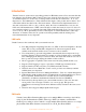
Virtual Connect 10/10D Module For latest specifications: Flex 10/10D Virtual Connect FlexFabric Module It is important to note how the external uplink ports on the Flexfabric module are configured. The graphic below outlines the type and speed each port can be configured as: Ports X1 – X8; Can be configured as 1Gb or 10Gb Ethernet or FCoE Ports X7 and or X8; are used for cross connections for horizontal stacking. Only one port is needed – two if you want redundancy. Uplink Ports X1-X8 support 0.
Virtual Connect Fibre Channel Modules Virtual Connect 24 Port Modules Virtual connect Fiber Channel modules come in a 24 port and port configuration. Both modules support 4 and 8 Gig Fibre Channel SFP’s.
Virtual Connect Manager The purpose of the Virtual Connect Manager (VCM) is to function as the single point of administration for the Virtual Connect Domain. This means that all aspects of configuring, managing, and monitoring the Virtual Connect Domain and all VC Ethernet and Fiber Channel modules is provided by VCM. VCM runs embedded on either the HP 10/10D or the HP Flex Fabric Ethernet modules when installed in interconnect any side by side interconnect bay.
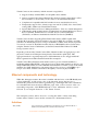
VC modules support the applicable groups of the following SNMP MIBs: Figure 12: Virtual Connect Port Descriptions The three types of ports are VC downlinks, VC uplinks, and internal cross-connects: VC Downlinks Ports that are directly connected to server NIC ports through the enclosure midplane. Only role is to provide connectivity to directly connected blade server NICs VC Uplinks Ports on the VC-Enet module faceplate that provide external connectivity for the VC domain.
to the various ports – IE ports that are not mapped cannot communicate. A VC Administrator defines vNets and, optionally, assigns VC uplinks to the vNets to provide external network connectivity. Once the vNets are defined, they are available for the Server Administrator to assign to server NIC ports. When a Server Admin moves a server profile from one server bay to another, the vNet assignments and, if used, managed MAC addresses (see section entitled “VC Managed MAC Addresses) are moved with the profile.
(see Appendix A for a description of the elements in the above diagram) Note: Layer 2 connectivity is defined as any two devices that can communicate with each other by directly exchanging Ethernet frames, carrying any protocol, without traversing a router or layer 3 switch. A layer 2 network could also be defined as a “broadcast domain”.
(see Appendix A for a description of the elements in the above diagram) An administrator can choose to manually configure a vNet (or Shared Uplink Set) for only fault tolerance by setting the vNet’s connection mode to ‘failover’. When a vNet’s connection mode is set to ‘failover’, the LACP protocol is disabled for the vNet and the administrator can change the VC uplink “Port Role” to “Primary” or “Secondary”.
“mode passive”. There are four types of scenarios for port trunking\channeling with Virtual Connect Uplink Ports: Same VC Module, Same External Switch, Same Port Channel Group When VC uplinks from the same physical VC-Enet module are assigned to the same vNet (or Shared Uplink Set) and are connected to ports on the same external Cisco switch that are assigned to the same port channel group and have the LACP protocol enabled, then VC will automatically form a single port channel.
(see Appendix A for a description of the elements in the above diagram) Note: Port channels can only form when VC uplink ports on the same physical VC Ethernet module are connected to the same external switch. VC does not support port channels that span across different VC Ethernet modules. Port Channeling (802.
single link in the port channel • Source IP address Identifies all conversations coming from the same IP address and load balances them all down a single link in the port channel • Destination IP address Identifies all conversations destined for the same IP address and load balances them all down a single link in the port channel • • • Source and Destination MAC address Identifies all conversations between two MAC addresses and load balances them all down a single link in the port channel Source and D
VC Uplinks and VLAN Trunking Virtual Connect supports VLAN tagging (trunking) on VC uplinks using IEEE 802.1Q and can be configured to support VLAN tagging on blade server NIC ports. VC Uplinks can operate in one of three modes: VLAN trunking mode Shared Uplink Set (SUS) plus tagging on external switch port When a VC uplink is a member of a SUS and is connected to a VLAN trunk port on an external switch, it operates as a VLAN trunk port.
default. In other words, the vNet keeps all frames within the same layer 2 domain (vNet), however, VC allows the frames to carry different VLAN tags from the external network all the way to the server NIC ports and vice versa. See VC Uplink 2 in the figure below. When VC uplink ports are assigned to a single vNet and connected to an external switch port in access mode, the VC uplink and vNet operate in access mode only carries untagged frames for a single VLAN (the access VLAN on the switch).
both servers, NIC 1 represents VLANs 2 thru 4. • All other NICs are not using VLAN tagging. All of these NICs are connected to a single VLAN (see color for VLAN association). NIC 1 on Server 1 can talk directly to NIC 1 on Server 2 without leaving the VC Domain. In order for NIC 2 on Server 1 to talk to NIC 2 on Server 2, the frames must first exit the VC Domain via VC uplink 1, transit the external switch on VLAN 2, and then re-enter the VC Domain on VC uplink 3.
server NIC ports. Virtual Connect also supports a feature called “SmartLink” that is enabled on vNets used by servers with NIC Teaming\bonding enabled. The SmartLink feature will disable the VC downlinks (server NIC ports) whenever all the VC uplinks for the associated vNet are unplugged. Basically, the SmartLink feature propagates a link-down event of a vNet’s uplinks to the server NICs in the team.
Additional Configuration details can be found at: Dual Hop FCOE with Virtual Connect HP Virtual Connect FlexFabric Cookbook HP Virtual Connect 1 GB Cookbook HP Virtual Connect for c-Class Blade System HP Virtual Connect for Cisco Network Administrators (version 4.
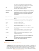
Figure 17: Dual-Hop FCOE configuration Figure 17 “Sample” Cisco Nexus Switch Configurations Nexus switch-A configuration Upgrade the first Nexus switch with minimum System version 5.2(1)N1(3) (enter: show version) Enable FCoE on the switch (disabled by default): configure terminal feature fcoe feature lacp Note: The Nexus will require a reload.
description FCoE uplink to FlexFabric channel-group 200 mode active lacp rate fast interface Ethernet1/6 description FCoE uplink to FlexFabric channel-group 200 mode active lacp rate fast Create the VLANs for the IP traffic: vlan 1,10,20 Create a trunk on the port channel interface to pass the FCoE (VLAN 200) and Ethernet traffic (VLAN 1,10,20): interface port-channel 200 switchport mode trunk switchport trunk allowed vlan 1,10,20,200 spanning-tree port type edge trunk Crea
Create zoneset: zoneset name zoneset1 vsan 200 member fcoe-zone Activate zoneset: zoneset activate name zoneset1 vsan 200 Nexus switch-B configuration Upgrade the second Nexus switch with minimum System version 5.2(1)N1(3) (enter: show version) Enable FCoE on the switch (disabled by default): configure terminal feature fcoe feature lacp Note: The Nexus will require a reload.
Create a virtual Fibre Channel interface to carry the FCoE traffic through eth1/5: interface vfc 2005 bind interface port-channel 200 no shutdown Assign the vfc interface and the Fibre Channel port to the FCoE VSAN: vsan database vsan 201 vsan 201 interface fc 2/1 vsan 201 interface vfc 2005 Configure the interface connected to the datacenter LAN: interface eth 1/17 switchport mode trunk switchport trunk allowed vlan 1,10,20 Configuration of the zone: Create zones: zone name
in regards to networking technology in order to better understand Virtual Connect. A Description of the VMware Components: Referencing the figure below, the VMware ESX server (left) is a single physical server running server virtualization software (VMware) that allows the physical server to host one or more instances of a virtual server, called a Virtual Machine (VM).
After comparing the components and their functionality, it is obvious why many customers treat a cClass enclosure with Virtual Connect the same way they would a single VMware ESX server. In other words, VC allows an entire enclosure to look to the network just like a big VMware ESX server. From a network redundancy and load balancing perspective, from a security perspective, from a port monitoring perspective, etc.
External network sees multiple MAC addresses on pNICs (VMware) or VC Uplinks Can be configured to isolate internal servers into separate Layer 2 domains (broadcast domains) (from VMs) (from blade servers) (uses internal loop prevention) (uses internal loop prevention) Can be configured to allow internal servers to communicate directly pNICs\VC Uplinks can be configured as Port Trunks (EtherChannel) pNICs\VC Uplinks can be configured as VLAN Trunks Does NOT transmits BPDUs to external network Does NOT p
for the associated VMs. Even though vSwitch 1 is redundantly connected to the Data Center LAN, no loops are formed. In addition, Spanning Tree is not needed between the ESX server and the Data Center LAN to prevent the loop. Instead, the NIC bonding technology on the ESX host prevents loops on the network by only allowing one logical path (single NIC port or single channel group\port trunk) to be active at one time. In comparison, VC uplinks prevent loops in the same manner.
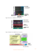
Figure 20. VC Stacking Link Recommendations Two Enclosure Three Enclosures HP Virtual Connect for Cisco Network Administrators (version 4.
Four Enclosures: HP Virtual Connect for Cisco Network Administrators (version 4.
Not Recommended: HP Virtual Connect for Cisco Network Administrators (version 4.
Optimizing Virtual Connect Stacking Links Virtual Connect stacking links provide the physical path between downlinks (server NIC ports) to VC uplinks. As a result, the fewer VC uplinks a frame has to traverse, the less latency the frame incurs in reaching the external network. Each VC module a frame must traverse adds approximately 3.8 microseconds of latency to the frame.
complexity of troubleshooting network related issues. • Server application licensing is maintained after hardware changes Many server application licensing mechanisms can key off the server’s MAC addresses. If the server’s MAC address changes (replacing a failed NIC, booting server image on a different physical server, etc.), then the application licensing may require re-licensing using the new MAC address. Virtualized MAC addresses do not prevent this problem.
• • • A server reverts to the factory-default MAC address when removed from the enclosure or when no VC Server Profile is applied to it. VC generates 2 MAC addresses per NIC port in order to support multi-function adapters that may require more than one MAC address per port. Customers requiring a centralized database for managing the VC managed MAC address pools should consider implementing Virtual Connect Enterprise Manager. See www.hp.com/go/vcem for more details.
If an Administrator needs the blade server NIC ports to receive layer 2 QoS markings (Class of Service), then the server NIC ports will need to be assigned to a vNet operating in 802.1Q\p tunneling mode. See the section above entitled “VC Uplinks and VLAN Trunking” for more information. Security ACLs & VLAN ACLs In the current version of firmware, Virtual Connect does not support user-configurable port or VLAN ACLs.
Figure 21: Using multiple vNets to force server-to-server traffic through external Cisco switch Port Security Many network administrators use a Cisco switch feature called “Port Security” to provide additional security on the network. This feature allows the administrator to control how many MAC address are learned on a particular switch port or allows the administrator to limit connectivity to specific MAC addresses.
addresses with a user-defined range will simply the task. Simply configure port security to allow the same range of MAC addresses that are manually configured for the user-defined range. Whether an administrator is configuring port security to allow a certain number of MAC address or to allow specific MAC addresses, they must configure all Cisco ports assigned to the same vNet (or Shared Uplink Set) with the same port security settings in order to eliminate communication problems after a VC uplink failover.
Figure 22: Using multiple vNets to extend PVLAN configuration from external Cisco switch (Please refer to Cisco documentation for a discussion of isolated, promiscuous, and community VLANs) Multicast & IGMP Snooping The IGMP Snooping feature allows VC-Enet modules to monitor (snoop) the IGMP membership activities of the blade servers and optimize a vNet’s handling of multicast traffic to maximize network resource utilization. Currently only IGMP v1 and v2 (RFC2236) are supported.
The monitor session must be configured with at least one ‘monitored port’ and a single ‘analyzer port’. The ‘monitor port’ list is the list of server downlinks whose traffic will be mirrored. The ‘analyzer port’ is the VC uplink port that the network analyzer is connected to. VC will mirror the traffic from the monitored ports to the analyzer port. A Port Monitoring session can mirror the traffic for up to 16 server downlinks to the analyzer port.
Additional Resources HP Services: www.hp.com/go/bladesystem/services BladeSystem Solutions: www.hp.com/go/bladesystem/solutions Virtual Connect Cookbook: www.hp.com/go/bladeconnect (see the Virtual Connect Interest Group) Virtual Connect Documentation: www.hp.com/go/bladesystem/documentation Virtual Connect Firmware: www.hp.com/go/bladesystemupdates HP NIC Teaming for Windows Whitepaper: ftp://ftp.compaq.com/pub/products/servers/networking/TeamingWP.
Appendixes Appendix A: Description of VC Network Diagram HP Virtual Connect for Cisco Network Administrators (version 4.
Appendix B: c3000 Port Mapping Diagram Server Bays Server Bays Half-Height Server Interconnect Bays Full-Height Server Interconnect Bays HP Virtual Connect for Cisco Network Administrators (version 4.
Appendix C: Frequently Asked Questions Q1: Why do I see lots of dropped frames (discards) on standby VC uplink ports? A1: An external switch has no concept of which VC link is the active uplink and which is the standby uplink. As far as the external switch is concerned, one of the uplinks is just a whole lot busier. That means that the external switch is still going to send some types of frames down the standby link and the standby link is going to discard them.
Q10: I noticed that the VC Ethernet module in interconnect bay 1 is the active Virtual Connect Manager and that the VC module in bay 2 is the standby. Does this mean that only the VC module in bay 1 is providing Ethernet connectivity for the blade servers? A10: No. Regardless of which VC module is running the active Virtual Connect Manager, all VC modules can be used simultaneously to provide network connectivity. Q11: Does VC support iSCSI? A11: Yes VC is compatible with iSCSI.
IPX, AppleTalk, etc.? A25: Virtual Connect only supports IP (IPv4) on its management interfaces (Web, SSH CLI, or SNMP). In reference to Virtual Connect’s bridging functionality, VC supports any layer 3 or higher protocol in use on blade servers. Since Virtual Connect is a layer 2 device, it is layer 3 protocol agnostic. Meaning, the blade servers can communicate through VC using any upper layer protocol (e.g. IPv4, IPv6, IPX, AppleTalk, etc.) that’s carried within an Ethernet frame.