
HP XC System Software Hardware Preparation Guide Version 3.1


Root Console Switch, This switch connects to the Root Administration Switch, Branch
Console Switches, and connects to the management console ports
of nodes in the utility cabinet.
Branch Administration Switch, This switch connects to the Gigabit Ethernet ports of compute nodes
and connects to the Root Administration Switch.
Branch Console Switch, This switch connects to the Root Console Switch and connects to
the management console ports of the compute nodes.
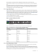
Table 2-1 lists the switch models that are supported for each use.
Table 2-1 Supported Switch Models
ProCurve Switch ModelSwitch Use
ProCurve 2848 or 2824Administration Switch
ProCurve 2650 or 2626Console Switch
2.3.2 Administrator Passwords on ProCurve Switches
The documentation that came with the ProCurve switch describes how to optionally set an administrator's
password for the switch.
If you define and set a password on a ProCurve switch, you must set the same password on every ProCurve
switch that is a component of the HP XC system.
During the hardware discovery phase of the system configuration process, you are prompted to supply
the password for the ProCurve switch administrator, and the password on every switch must match.
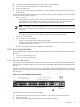
2.3.3 Switch Port Connections
Most HP XC systems have at least one Root Administration Switch and one Root Console Switch. The
number of Branch Administration Switches and Branch Console Switches depends upon the total number
of nodes in the hardware configuration.
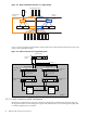
The Administration Network using the root and branch switches must be parallel to the Console Network
root and branch switches. In other words, if a particular node uses port N on the Root Administration
Switch, its management console port must be connected to port N on the Root Console Switch. If a particular
node uses port N on the Branch Administration Switch, its management console port must be connected
to port N on the corresponding Branch Console Switch.
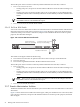
A graphical representation of the logical layout of the switches and nodes is shown in Figure 2-2.
2.3 Switches 21