
HP XC System Software Hardware Preparation Guide Version 3.1
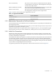
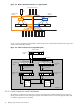
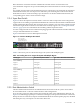
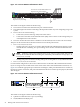
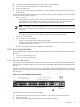
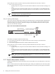
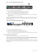
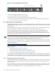


Figure 2-2 Node and Switch Connections on a Typical System
Compute Nodes
Br anch Switches
Administration
Root
Console
Root
Head
Node
Specialized Role Nodes
Console
Switches
Administration
Switches
Br anch Switches
Figure 2-3 shows a graphical representation of the logical layout of the switches and nodes in a large-scale
system with a Super Root Switch.
Figure 2-3 Switch Connections for a Large-Scale System
Super Root
Switch
ProCurve 2848
1 2 46
48
Ports 3 - 45
ProCurve 2848
ProCurve 2848
1 2 46
48
Ports 3 - 45
ProCurve 2650
ProCurve 2650
1 2 48
50
Ports 3 - 47
1 2 46
48
Ports 3 - 45
1 2 48
50
Ports 3 - 47
Ethernet
CP
Port
Node 1
Ethernet
CP
Port
Node 2
To Region 2
Root Admin
Switch
Branch Admin
Switch
Root Console
Switch
Branch Console
Switch
Region 1
To Next Switch To Next Switch
2.3.3.1 Switch Connections and HP Workstations
HP model xw workstations do not have console ports. Only the Root Administration Switch supports
mixing nodes without console management ports with nodes that have console management ports (that
is, all other supported server models).
22 Making Node and Switch Connections