
HP XC System Software Hardware Preparation Guide Version 3.1

4. Ensure that all hardware components are running the correct firmware version and that all nodes in
the system are at the same firmware version. See “Firmware Requirements and Dependencies”
(page 31) for more information.
The hardware preparation steps described in this chapter apply only if the nodes are running the
latest validated firmware version.
5. Review the documentation that came with the hardware and have it available, if needed.
Depending upon the type of cluster platform, proceed to one of the following sections to prepare individual
nodes:
• “Preparing the Hardware for CP3000 Systems” (page 33)
• “Preparing the Hardware for CP3000BL Systems” (page 44)
• “Preparing the Hardware for CP4000 Systems” (page 45)
• “Preparing the Hardware for CP6000 Systems” (page 55)
3.4 Preparing the Hardware for CP3000 Systems
Follow the procedures in this section to prepare each node before installing and configuring the HP XC
System Software. Proceed to the following sections, depending on the hardware model:
• “Preparing HP ProLiant DL140 G2 and G3 Nodes” (page 33)
• “Preparing HP ProLiant DL360 G4 and G5 Nodes” (page 36)
• “Preparing HP ProLiant DL380 G4 and G5 Nodes” (page 38)
• “Preparing HP xw8200 and xw8400 Workstations” (page 41)
3.4.1 Preparing HP ProLiant DL140 G2 and G3 Nodes
Use the BIOS Setup Utility to configure the appropriate settings for an HP XC system on HP ProLiant
DL140 G2 and DL140 G3 servers.
For these hardware models you cannot set or modify the default console port password through the BIOS
Setup Utility, as you can for other hardware models. The HP XC System Software Installation Guide documents
the procedure to modify the console port password. You are instructed to perform the task just after the
discover command discovers the IP addresses of the console ports.
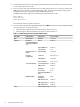
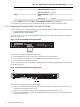
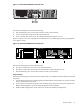
Figure 3-1 shows a rear view of the HP ProLiant DL140 G2 server and the appropriate port assignments
for an HP XC system.
Figure 3-1 HP ProLiant DL140 G2 and DL140 G3 Server Rear View
HPTC-0144
LO100i
321
The callouts in the figure enumerate the following:
1. This port is used for the connection to the Administration Switch (branch or root). On the back of the
node, this port is marked with the number 1 (NIC1).
2. If a Gigabit Ethernet (GigE) interconnect is configured, this port is used for the interconnect connection.
Otherwise, it is used for an external connection. On the back of the node, this port is marked with
the number 2 (NIC2).
3. This port is used for the connection to the Console Switch. On the back of the node, this port is marked
with LO100i.
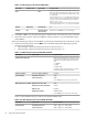
Setup Procedure
Perform the following procedure for each HP ProLiant DL140 G2 and DL140 G3 node in the HP XC system.
Change only the values described in this procedure; do not change any other factory-set values unless
you are instructed to do so. Follow all steps in the sequence shown:
3.4 Preparing the Hardware for CP3000 Systems 33