
Instruction Manual
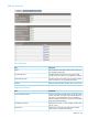


GPSM Bay Information tab
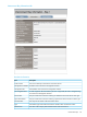
Device information
DescriptionItem
The common descriptive name of the GPSM.Product Name
The part number to be used when ordering an additional GPSM of this type.Part Number
The part number to be used when ordering a replacement GPSM of this type.Spare Part Number
The unique serial number of the GPSM.Serial Number
Manufacturing information about the GPSM.Engineering Date Code
The name of the company that manufactured the GPSM.Manufacturer
Now configured firmware version on the GPSM.Complex Firmware
Version
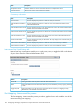
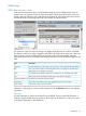
GPSM Virtual Buttons
GPSM virtual buttons enables you to toggle the UID on the GPSM of your choice from the Onboard
Administrator GUI.
Click the Toggle On/Off button to turn UID on the GPSM on (blue) or off (gray) for easy identification
of the selected GPSM.
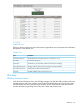
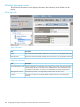
Enclosure power management
Planning power management
The compute enclosures each contain twelve power supplies (six upper and six lower), which are
monitored directly by Onboard Administrator. At least one upper and one lower power supply
must be installed at all times.
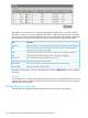
Onboard Administrator is responsible for calculating the redundancy status, total available power,
and total power consumed. This information is displayed to the user and is used to manage power
resources. The Onboard Administrator power subsystem displays include status and information
for each power supply, and the power enclosure itself.
Also included in the power fault realm is control of the electronic fuses between the power backplane
and the server or switch bays. The Onboard Administrator will alert on fuse trips to enable you to
reset fuses manually.
When installing additional power supplies into the enclosure, different power supply part numbers
are not supported in the same enclosure. The Onboard Administrator identifies which power
supplies must be replaced by displaying a caution icon.
Enclosure power management 129