
Implementing RemoteFX on HP ProLiant Servers

7
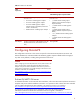
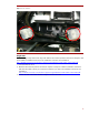
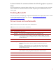
4. Connect the other end of the cable to either power connector P9 or P12. For more information on the
cable installation, refer to the cable labels and the documentation included with the cable kit.
Figure 2: Single-GPU configuration
5. Replace the black plastic plate and fan cage. For instructions on replacing parts, refer to the HP
ProLiant DL/ML370 G6 Server Maintenance and Service Guide. The maintenance and service guide is
available at
http://bizsupport2.austin.hp.com/bc/docs/support/SupportManual/c01711820/c01711820.pdf.
Two homogenous GPUs
To install two GPUs, follow these steps and refer the HP ProLiant DL/ML370 G6 Servers Graphics card
power cable kit Installation Instructions. The installation instructions are available at
http://h20000.www2.hp.com/bc/docs/support/SupportManual/c02475365/c02475365.pdf.
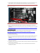
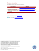
1. Insert the first GPU into slot 3.
2. Insert the second GPU into slot 8.
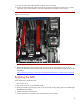
3. Refer to the HP ProLiant DL/ML370 G6 Servers Graphics card power cable kit Installation Instructions
and select two cables with pin connectors that match your GPU. The installation instructions are
available at
http://h20000.www2.hp.com/bc/docs/support/SupportManual/c02475365/c02475365.pdf.
4. For the GPU in slot 3, connect one end of the cable to the GPU (as marked on the cable) and the other
end to power connector P9.
5. For the GPU in slot 8, connect one end of the cable to the GPU (as marked on the cable) and the other
end to the power connector P12.
6. For more information on the cable installation, refer to the cable labels and the documentation
included with the cable kit.