
User's Manual

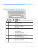
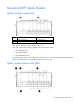
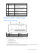
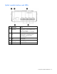
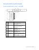

Table Of Contents
- HP Moonshot Switch User and Maintenance Guide
- Abstract
- Notice
- Contents
- Component and LED identification
- Operations
- Setup
- Configuration
- Troubleshooting
- Illustrated parts catalog
- Removal and replacement procedures
- Regulatory information
- Electrostatic discharge
- Support and other resources
- Acronyms and abbreviations
- Documentation feedback
- Index

Component and LED identification 7
Item Description Status
1
Uplink module UID
LED/button
Solid blue = Switch module ID is selected.
Flashing blue = Switch module firmware
update is in progress.
Off = Switch module ID is not selected.
2
Uplink module health
LED
Green = Normal operation
Flashing amber = Degraded condition
Flashing red = Critical condition
Off = No power
3
Uplink module link
LED
Solid green = Link
Off = No link
4
Uplink module
activity LED
Flashing green = Activity
Off = No activity
5
Reset button Resets the switch module
Moonshot-4QSFP+ Uplink Module
Uplink module components
Item Component Description
1
Serial console port For management
2
QSFP+ ports Q1–Q4 40Gb Ethernet
QSFP+ ports Q1 through Q4 support Ethernet traffic only.
QSFP+ ports support the following pluggable Ethernet transceiver modules:
• HP 40GBASE QSFP+
• HP 40GBASE QSFP+ SR4
• HP 40GBASE QSFP+ DAC
• HP 40GBASE QSFP+ to 4x10G SFP+
Any available port can be used to connect to the data center. Ensure the port is populated with supported HP
transceiver modules that are compatible with the data center port type.