HP RPG/XL Programmer’s Guide HP 3000 MPE/iX Computer Systems Edition 1 Manufacturing Part Number: 30318-90001 E1288 U.S.A.
Notice The information contained in this document is subject to change without notice. Hewlett-Packard makes no warranty of any kind with regard to this material, including, but not limited to, the implied warranties of merchantability or fitness for a particular purpose. Hewlett-Packard shall not be liable for errors contained herein or for direct, indirect, special, incidental or consequential damages in connection with the furnishing or use of this material.
HP RPG/XL Programmer's Guide Product 900 Series HP 3000 Computers HP RPG/XL Programmer's Guide Printed HP Part Edition Printed in U.S.A. No. 30318-90001 E1288 Dec 1988 Notice The information contained in this document is subject to change without notice. HEWLETT-PACKARD MAKES NO WARRANTY OF ANY KIND WITH REGARD TO THIS MATERIAL, INCLUDING, BUT NOT LIMITED TO, THE IMPLIED WARRANTIES OF MERCHANT ABILITY AND FITNESS FOR A PARTICULAR PURPOSE.
Preface The HP RPG/XL Programmer's Guide explains how to perform many of the common programming functions in RPG. It does not include an exhaustive discussion of these tasks, but covers the commonly-used ones and the ones that use features unique to Hewlett-Packard computers. This manual is directed to experienced RPG programmers, who may or may not be familiar with Hewlett-Packard computers. The manual discusses the language features available with the MPE XL operating system.
an RPG program. Native Language Programmer's Guide (32650-90022) - This manual discusses how to create and use Native Language Support message files. Message Catalogs Programmer's Guide (32650-90021) - This manual discusses how to create and use non-Native Language Support message files. FCOPY Reference Manual (03000-90064) - This manual explains how to use the FCOPY file utility. SORT-MERGE/XL Programmer's Guide (32650-90080) - This manual explains how to use the SORT/MERGE file utility.
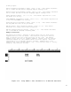
Comments 1 This line makes indicator 20 available to an external subroutine. Columns 43-48 specifies that indicator 20 is passed to the external subroutine. (Prefix indicator names by IN.) P- 4 2 This line makes the field, PNAME, available to an external subroutine. 3 This line executes the external subroutine, SUB01.
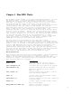
Chapter 1 How RPG Works RPG programs can be thought of as having two different authors. You are the primary author. You enter the RPG program specifications that describe the input and output data and the calculations to perform on that data. For example, if you want to print a total line on a report, you must describe the format of the total line and define the calculations that will produce it. The RPG compiler is the second author of RPG programs.
The Basic RPG Logic Cycle Specifications that you enter in an RPG program are executed in the order determined by the RPG compiler. The RPG compiler fits your specifications into the standard logic framework, producing a complete program. It is important to understand the RPG-supplied logic to effectively use many features of RPG. The RPG logic cycle has three phases which are repeated for each record that is processed.
RPG Indicators RPG turns indicators on and off during the RPG logic cycle to indicate that certain processing events have occurred. You can use the settings of the indicators to select the specifications to perform in your program. For instance, control fields trigger total operations such as printing total lines on a report. To define a control field, you assign a control-level indicator (L1-L9) to it on the Input Specification. When this input field changes, RPG turns on the control-level indicator.
Control-Level (L1-L9) Lets you sense and perform total operations, such as printing part number totals on a report. First-Page (1P) Lets you sense when the first record is processed and lets you perform first record processing. Function Key (F1-F9) Lets you use function keys with VPLUS and with the Calculation Specification operations, SET, DSPLY and DSPLM. General (01-99) Lets you control operations on Input, Calculation and Output Specifications.
initialized and the 1P and L0 indicators are turned on. All files are prepared for processing and all preexecution-time tables and arrays are read into memory. First-page alignment is performed for printer files and all output controlled by the 1P indicator is written. A record is read from each primary and secondary input file. The program is now ready to begin the main logic cycle. 2 Heading and Detail-Time Output This begins the main logic cycle.
first record with control level fields, the program performs total-time calculations and output (including total-time overflow output). Total-time operations are all those calculations with L0-L9 or LR indicator entries in the Control Level Field (columns 7-8) and output operations of record type T. These operations are done after each control break occurs or after the last input record is read, but before the information on the input record selected in Step 4 is actually made available for processing.
Pre-cycle Installation and 1 Housekeeping 8 Detail-time Calculations 7 Data movement Detail Time Total Time 6 2 Heading and detail-time output Input Time Record Input Total-time Operations Control break test 5 Figure 1-3. 3 Record Selection 4 The Primary Steps in the RPG Logic Cycle Substeps in the RPG Logic Cycle This section describes in detail each step of the RPG logic cycle including when indicators are turned on and off.
1A All data areas are initialized. This includes compile-time tables and arrays and the user date (UDATE) fields obtained from the system. User indicators (U1-U8) are fetched from the specified source. The Local Data Area (LDA) is initialized with the contents of LDAFILE, if specified. The 1P and L0 indicators are turned on. All files, including TurboIMAGE databases and data sets, are opened unless the program has been suspended by the JCW RPGSUSP (see "End-of-Job Processing", Step E-2B).
4A. 3F If the record just read contains an unidentified record type, or an incorrect record sequence (as specified in the Group Sequence Field of the Input Specification), control skips to "Run-Time Error Processing", Step E-1. 3G If the record just read is a blank spread record, control goes back to Step 3D. 4 Record Selection 4A The next record is selected for processing.
Field of one or more Input Specifications, a record is retrieved from each specified file; the appropriate record-identifying indicators are turned on; the data fields are moved to the input data area and field indicators are set. 7E 8 If look-ahead fields are specified, the look-ahead fields are extracted and moved to the look-ahead data area.
Chapter 2 Creating an RPG Program You can create an RPG program using any editor or word processor that produces a standard ASCII file. For example, you can use EDITOR. EDITOR comes with your HP system, produces a standard text file and is widely used for other applications. Another popular editor is TDP. Instead of EDITOR or TDP, you may want to use the RPG Interactive System Environment (RISE). RISE is specifically designed for entering RPG programs and lets you use the entire screen.
22
Chapter 3 Using Disc Files in an RPG Program RPG contains language elements that let you process several kinds of disc files. You can use MPE files, Keyed Sequential Access Method (KSAM) files and TurboIMAGE databases. The following list summarizes these files and how you can use them in RPG programs: File type: Ways you can access the file: MPE Sequentially, randomly. KSAM Sequentially, sequentially within key limits, randomly and chronologically.
* No automatic maintenance of data relationships * Extra memory usage when several users access the same file simultaneously Creating a KSAM Disc File There are three ways to create a KSAM disc file: Use this method: KSAMUTIL When: You want to build an empty KSAM file or when you cannot use an RPG program to build it (RPG programs won't let you specify more than one key field, for instance). (KSAMUTIL is a KSAM utility that creates an empty KSAM file.
Manual.) For example, the following command copies 50 records (records 0 through 49) from the KSAM file, TRANSFL, to the KSAM file, MASTFL. MASTFL is a new file and is created along with its key file, MASTFLK. FCOPY FROM=TRANSFL;TO=(MASTFL,MASTFLK);SUBSET=0,49 If MASTFL and its key file already exist, the following command can be used to copy the first 50 records in TRANSFL to it. FCOPY FROM=TRANSFL;TO=MASTFL;SUBSET=0,49 NOTE You can create an empty KSAM file by specifying SUBSET=0,0 in the FCOPY command.
Figure 3-2. Creating a KSAM File Within an RPG Program Comments Comments 1 This line defines the input customer transaction file, TRANSFL. 2 This line defines the master transaction file, MASTFL. Column 15 is O to indicate that the file is an output file. Columns 20-23 are blank to specify that there is one record per block. Columns 24-27 contain 256 to specify the number of characters per record. Columns 29-30 contain 5 to specify the number of characters in the key field.
Reading a KSAM Disc File There are several ways to read records in a KSAM file. Three methods, sequential, random and chronological, are discussed in this chapter. Reading a file sequentially means that RPG retrieves records automatically in key sequence. You can process the entire file automatically or you can process a portion of the file. To process part of the file, you give RPG the key value of the first record to access.
Column 31 contains A to specify that the key field is alphanumeric. Column 32 contains I to specify that this is a KSAM file. Columns 35-38 contain 1 to specify the starting location of the key field. Reading a KSAM File Sequentially by a Non-Key Field This section explains how to read an entire KSAM file sequentially by a non-key field. You can use any field that was not defined as a key when the file was created. (This method of reading KSAM files also applies to MPE files.
Columns 24-27 specify the record length, 4. (XSORT always creates ADDROUT records that are four bytes long.) Columns 29-30 contain the key field length, 4. Column 32 is T to specify that this is an ADDROUT file. Column 39 is E to indicate that there is a File Extension Specification for this file. 2 This line defines the KSAM file, MASTFL. Column 28 is R to indicate that MASTFL is accessed randomly. Column 31 is I to specify that records in MASTFL are accessed by their record addresses.
Figure 3-5. Full Key Values Reading a KSAM File Sequentially Within Key Limits - Supplying Comments 1 This line defines the KSAM file, MASTFL. Column 16 is D to indicate that MASTFL is a demand file. Column 28 is L to specify that MASTFL will be processed within key limits. Columns 29-30 contain 15 to specify the length of the secondary key, LNAME. Column 31 contains A to specify that the secondary key is an alphanumeric key. Column 32 contains I to specify that this is a KSAM file.
standard text editor, for example EDITOR. Enter key ranges starting with position one. Enter the lower key value first followed immediately by the upper key value. (See the HP RPG Reference Manual for details on creating a RAF.) _____________________________________ | | | 00050100 | | 12001280 | | 20002475 | | 50005999 | | | | | _____________________________________ Figure 3-6.
Supplying Partial Key Values Figure 3-8 shows how to read all records in a KSAM file having a range of key values. All records in the KSAM file, MASTFL, are read that have last names starting with a specific character (for example "A"). A user at a terminal enters the letter and the program reads the first record in alphabetical sequence that starts with the letter. When there are no more records in the file, the user is prompted to enter another letter.
Column 16 is D to indicate that MASTFL is a demand file. Column 28 is L to specify that MASTFL will be processed within key limits. Columns 29-30 contain 15 to specify the length of the secondary key (last name). Column 31 contains A to specify that the secondary key is an alphanumeric key. Column 32 contains I to specify that this is a KSAM file. 2 This line specifies the starting secondary key value for reading MASTFL.
Figure 3-9. Reading a KSAM File Randomly by Key Comments 1 This line defines the KSAM file, MASTFL. Column 16 contains C to indicate that the KSAM file is accessed in chained fashion. Column 28 is R to specify random processing. Columns 29-30 contain 4 to specify the key length. Column 31 contains A to specify that the key is alphanumeric. Column 32 contains I to specify that this is a KSAM file. 2 This line reads MASTFL by primary key. Columns 18-21 contain the name of the key field, DEPT.
_____________________________________ | | | 00060010002800120013 | | 00160020 | | 00360040 | | 0026001100290030 | | 0080 | | | _____________________________________ Figure 3-10. Reading a KSAM File Randomly by Primary Key - RAF Entries The KSAMUTIL entries to create a file that can be accessed randomly is shown in the previous section "Reading a KSAM File Randomly".
file as a CHAINed file and as a demand file in the same program. To read randomly and sequentially by the same key define the file as a full procedural file in the File Description Specification. Figure 3-12 show how to read a KSAM file randomly and sequentially using the key field, DEPT. A department number is entered by a user from the terminal. The program randomly reads the KSAM file, MASTFL, to access that department.
Reading a KSAM File Randomly and Sequentially Using Different Keys. This section explains how to access a file both randomly and sequentially using different key fields. There are two ways to do this. For both methods you describe the files in the program as if they were two separate entities. In the first method, enter two FILE commands (file equations ) before executing the program. This method is easier to use and less likely to result in access conflicts than the second method.
Column 32 is I to specify that this is a KSAM file. 2 This line defines the KSAM file, MASTERD. Column 16 is D to indicate that MASTERD is a demand file. Column 28 is L to specify that MASTERD will be processed within key limits. Column 32 contains I to specify that this is a KSAM file. 3 This line reads MASTERC randomly by department number, DEPT. Columns 28-32 are CHAIN to specify that chained (sequential) processing be performed for the file MASTERC. The key is DEPT.
Figure 3-14. Reading a KSAM File Randomly and Sequentially - Using File Description Continuation Lines Comments 1 This line defines the KSAM file, MASTERC. Column 16 is C to indicate that the file is processed in a CHAINed fashion. Column 28 is R to indicate that MASTERC is processed randomly. Column 32 is I to specify that This is a KSAM file. 2 This line equates the KSAM file, MASTERD to MASTFL. Column 53 is K to indicate that this line is a Continuation line for MASTERC.
is to be used for MASTERD. 5 This line reads MASTERC randomly by department number, DEPT. Columns 28-32 are CHAIN to specify that chained (random) processing be performed for the file MASTERC. The key is DEPT. 6 This line starts the code that processes MASTERD sequentially by secondary key. Columns 28-32 are SETLL to set the beginning secondary key value for MASTERD. SETLL set the file pointer to the key value placed in LNAME.
Comments 1 This line defines the KSAM file, MASTFL. Column 17 is E to specify that processing proceed to the end of the file. Column 32 contains C to indicate the file that the file be processed in chronological order. Updating a KSAM Disc File This section shows how to randomly update a KSAM file using its primary key. Figure 3-17 lists a program that updates a customer master file (MASTFL) for a large department store. The master file is updated by a daily sales transaction file (TRANSFL).
Comments 1 This line defines the sales transaction file, TRANSFL. This file is an MPE file. 2 This line defines the KSAM customer master file, MASTFL. Columns 7-14 contain the name of the customer master file, MASTFL. Column 15 is U to indicate that MASTFL will be updated. Column 16 is C to indicate that MASTFL will be processed in a chained fashion. Column 28 is R to specify that MASTFL will be processed randomly. 3 MSGFL is a message file that is used to report program and other errors.
deleted record is encountered in MASTFL. 12 The message, DELETED/OBSOLETE RECORD, is printed when indicator 03 is on. 13 This line defines the second record format for the message file, MSGFL. Columns 27-28 contain 60 to print an error message when a record is not found in MASTFL. 14 NOTE The message MISSING RECORD, is printed when indicator 60 is on. The CHAIN operation in line 7 turns on indicator 60 when a record is not found for the key.
1 This line defines the KSAM file, MASTFL. Column 16 is U to indicate that the KSAM file will be updated. Column 17 is C for CHAINed (random) access. Column 66 is A to indicate that records will be added to the file. 2 This line reads MASTFL randomly. Columns 18-27 contain DEPT to specify the primary key field for MASTFL. Columns 28-32 contain CHAIN to read a record randomly. Columns 54-55 contain 80 to turn on indicator 80 when a record is not found in MASTFL.
Figure 3-19. Deleting Records From a KSAM File Comments 1 This line defines the KSAM file, MASTFL. Column 15 is U to indicate that the file will be updated. 2 This line reads the KSAM file, MASTFL, in a chained fashion. Columns 18-27 contain EMPNO, which is key field name. Columns 28-32 contain CHAIN to specify a CHAINed read operation. Columns 33-42 contain MASTFL to name the KSAM file. 3 This line performs exception output when the appropriate record in MASTFL is found.
in your program. When you close the file, or when your program finishes, the file is available to others. For example, entering this FILE command before running a program gives the program exclusive access to the file, MASTER: :FILE MASTER;EXC * Semi-exclusive Semi-Exclusive access lets others read a file but prevents them from updating it. When you close the file, or when your program finishes, the file is available to others.
Figure 3-20. Automatically Locking and Unlocking KSAM Files Comments 1 This line defines KSAM file, MASTFL, as an Update CHAINed file. 2 This line enables the automatic lock facility for MASTFL. Column 53 is K to indicate that this is a Continuation line. Columns 54-59 are LOCK to enable RPG automatic locking. 3 The line reads MASTFL randomly by department number, DEPT. 4 This line directs RPG to perform exception output when a department record is not found (indicator 80 is turned on).
Figure 3-21. Manually Locking and Unlocking KSAM Files Comments 1 This line defines the KSAM file,MASTFL, as an Update CHAINed file. 2 This line enables the manual locking facility for the file, MASTFL. Column 53 is K to indicate that this is a Continuation line. Columns 54-59 are NOLOCK to enable RPG manual locking. 3 This line locks the file, MASTFL, before a record is read from it. Columns 28-32 contain LOCK. This locks MASTFL before the chain operation (next line).
Database Disc Files (TurboIMAGE) The following list summarizes the advantages and disadvantages of using TurboIMAGE databases. For detailed information on TurboIMAGE, see the TurboIMAGE/XL Database Management System manual.
[ERROR: ] Click here to view figure. Figure 3-22. The MARKET Database Creating a TurboIMAGE Database There are database. data sets root file data into detail. four steps to creating and loading data into a TurboIMAGE First, you create a schema file that defines the database, its and data items. Next, you build the database by creating a and then running DBUTIL. Finally, you write a program to load the database. The next sections explain each of these steps in Defining a TurboIMAGE Database Schema.
Figure 3-23.
Figure 3-23.
. Figure 3-23.
Figure 3-23.
Creating a TurboIMAGE Root File. Once you define a TurboIMAGE schema, you then create a TurboIMAGE root file. For example, to create the root file for our sample MARKET database, enter these commands at the operating system colon prompt: :FILE DBTEXT=MARKET.PUB :FILE DBSLIST=$STDLIST :RUN DBSCHEMA.PUB.SYS;PARM=3 If there are any schema or execution errors, they are displayed next. When the root file is successfully created, you see the message END OF PROGRAM.
Figure 3-24.
. Figure 3-24. Loading a TurboIMAGE Database (Continued) Comments 1 This line defines the accounts file, ACCTSIN. 2 This line defines the TurboIMAGE data set file, DACCOUNT. Column 31 is A to indicate that DACCOUNT has an alphanumeric key. Column 32 contains M to indicate that DACCOUNT is a TurboIMAGE file. 3 This line specifies that DACCOUNT is part of the MARKET database. Column 53 is K to indicate that this line is a Continuation line.
* Sequentially (not in key order) * Sequentially by full key values * Randomly by key value Reading a TurboIMAGE Data Set Sequentially. Since TurboIMAGE does not maintain the sequential order of keys in its data sets, you cannot read the entire data set from beginning to end by a specific key. However, you can retrieve all of the records in their stored unsorted sequence. This may be useful, for example, for extracting data set records for a sort.
that permits read access to the database. 4 This line defines the data set to be used. Columns 54-65 contain DSNAMED-ACCOUNTS to identify the data set, D-ACCOUNTS. 5 This line begins the input record description of the DACCOUNT file. 6 This line begins the output record description of the DISPLAY file. Reading a TurboIMAGE Data Set Sequentially By Key. This section explains how to read all records in a detail data set having a specific key value.
Figure 3-26.
Figure 3-26. Reading a TurboIMAGE Data Set Sequentially by Key (Continued) Comments 1 This line defines the TurboIMAGE data set file, DACCOUNT. Columns 28-38 indicate that DACCOUNT is a TurboIMAGE file to be processed randomly by the NAME-LAST key field (positions 19-34). 2 This line specifies that DACCOUNT is part of the MARKET database. Columns 54-65 identify MARKET as the TurboIMAGE database that is used. Column 66 is 6 to indicate Open Mode 6 - Shared Read Access.
Columns 28-32 contain CHAIN to specify a "dummy" chained read operation. This operation simply establishes a new head of chain. Columns 33-42 specify the name of the TurboIMAGE data set file, DACCOUNT. 8 This line is the beginning of the loop that reads records in the D-ACCOUNTS data set. 9 This line reads records randomly from the D-ACCOUNTS data set. Columns 18-27 contain INAME to specify the key field. Columns 28-32 contain CHAIN to specify a chained read operation.
Comments 1 This line defines, AACCOUNT, which is a TurboIMAGE automatic master data set. Columns 28-38 indicate that AACCOUNT is a TurboIMAGE file to be processed randomly by the ACCOUNT-NO key field (positions 1-6). 2 This line specifies that AACCOUNT is part of the MARKET database. Columns 54-65 identify MARKET as the TurboIMAGE database that is used. Column 66 is 6 to indicate Open Mode 6 - Shared Read Access. Column 67 is 7 to specify Input/Output Mode 7 - Calculated Read.
Figure 3-28 shows how to access records in the TurboIMAGE data set D-ACCOUNTS (see the schema for this data set in Figure 3-23) by its key, and change the TYPEC field in those records. Figure 3-28. Randomly Updating Records in a TurboIMAGE Data Set Comments 1 This line defines the file, INPUT. 2 This line defines the TurboIMAGE data set file, DACCOUNT. Column 15 is U to indicate that DACCOUNT is updated. Column 16 is C for chained (random) access.
6 This line names the data set to be accessed. Columns 54-65 contain DSNAMED-ACCOUNTS to specify that the data set is D-ACCOUNTS. 7 This line begins the input record description of the INPUT file. 8 This line begins the input record description of the DACCOUNT file. 9 This line reads the data set, D-ACCOUNTS, randomly. Columns 18-27 contain ACTNO to specify the key field for reading the data set. Columns 28-32 contain CHAIN to specify a chained read operation.
Figure 3-29. Randomly Adding Records to a TurboIMAGE Data Set Comments 1 This line defines the IDACCT file. 2 This line defines the TurboIMAGE data set file, DACCOUNT. Column 15 is U to indicate that DACCOUNT is updated. Column 16 is C for chained (random) access. Column 66 is A to indicate that records are added to DACCOUNT. 3 This line specifies that DACCOUNT is part of the MARKET database. Columns 54-65 identify MARKET as the TurboIMAGE database that is used.
set is D-ACCOUNTS. 7 This line begins the input record description of the IDACCT file. 8 This line begins the input record description of the DACCOUNT file. (Since records are being added only, you do not need to define input fields.) 9 This line reads the data set, D-ACCOUNTS, randomly. Columns 18-27 contain ACTNO to specify the key field for reading the data set. Columns 28-32 contain CHAIN to specify a chained read operation. Columns 33-42 specify the name of the TurboIMAGE data set file, DACCOUNT.
Figure 3-30. Deleting Records from a TurboIMAGE Data Set Comments 1 This line defines the file, INPUT. 2 This line defines the TurboIMAGE data set file, DACCOUNT. Column 15 is U to indicate that DACCOUNT is updated. Column 16 is C for CHAINed (random) access. 3 This line specifies that DACCOUNT is part of the MARKET database. Columns 54-65 identify MARKET as the TurboIMAGE database that is used. Column 66 is S to indicate Open Mode S - Data Set Locking for Duration.
8 This line begins the input record description of the DACCOUNT file. 9 This line reads the D-ACCOUNTS data set randomly. Columns 18-27 contain ACTNO to specify the key field. Columns 28-32 contain CHAIN to specify a chained read operation. Columns 54-55 contain 80 to turn on indicator 80 when a record is not found for the account number in D-ACCOUNTS. Columns 56-57 contain the H0 indicator to avoid a compiler warning for the CHAIN operation.
--------------------------------------------------------------------------------------------| | | | 9 | Lock the data set before a record is read, written or updated. | | | Unlock it after the record is read, written or updated. | | | | --------------------------------------------------------------------------------------------| | | | R | Lock the data record before it is read, written or updated. Unlock | | | it after the record is read, written or updated.
set is D-ACCOUNTS. Manually Locking and Unlocking TurboIMAGE Databases and Data Sets. section explains how you can control the locking and unlocking of TurboIMAGE databases and data sets. You use the LOCK and UNLCK operations in Calculation Specifications. This Figure 3-30 through Figure 3-32 show how to lock and unlock databases, data sets and individual records in the data sets. The examples use the MARKET database whose schema is shown in the section titled "Defining a TurboIMAGE Database Schema.
Column 67 is C to specify chained sequential read mode. 4 This line defines the password for the database. Columns 54-65 contain LEVEL WRITER to specify password, WRITER. This password establishes a user class identification that permits write access to the database. 5 This line identifies the key field for the data set. Columns 54-65 contain ITEM ACCOUNT-NO to specify that the key for the data set is ACCOUNT-NO. 6 This line names the data set to be accessed.
11 This line specifies that exception output is performed when indicator 0 is turned on. 12 This line unlocks the database, MARKET, when indicator 80 is turned on. Columns 10-11 contain 80 to condition the UNLCK operation. Columns 28-32 contain UNLCK to specify the unlock operation. Columns 33-42 contain DACCOUNT to identify the data set to unlock. Columns 43-48 contain MARKET to identify the database to unlock. Column 51 is 1 for the field length (always use 1).
Figure 3-33. Manually Locking and Unlocking a TurboIMAGE Data Set Comments 1 This line defines the file, IDACCT. 2 This line defines the TurboIMAGE data set file, DACCOUNT. Column 15 is U to indicate that DACCOUNT is updated. Column 16 is C for CHAINed (random) access. Column 66 is A to indicate that records are added to DACCOUNT. 3 This line specifies that DACCOUNT is part of the MARKET database. Columns 54-65 identify MARKET as the TurboIMAGE database that is used.
WRITER. This password establishes a user class identification that permits write access to the database. 5 This line identifies the key field for the data set. Columns 54-65 contain ITEM ACCOUNT-NO to specify that the key for the data set is ACCOUNT-NO. 6 This line names the data set to be accessed. Columns 54-65 contain DSNAMEA-ACCOUNT-NO to specify that the data set is D-ACCOUNTS. 7 This line begins the input record description of the IDACCT file.
Columns 28-32 contain UNLCK to specify the unlock operation. Columns 33-42 contain DACCOUNT to identify the data set to unlock. Columns 56-59 contain the same indicators used in line 10 and they function the same way. 13 This line specifies the output operation for adding records to the D-ACCOUNTS data set. Column 15 is E to identify this record as an exception record. Columns 16-18 are ADD to add records to the TurboIMAGE data set.
Columns 54-65 identify MARKET as the TurboIMAGE database that is used. Column 66 is L to indicate user-controlled manual locking. Column 67 is C to specify chained sequential read mode. 4 This line establishes write access to the database. Columns 54-65 contain LEVEL WRITER to specify write access to the database. 5 This line identifies the key field for the data set. Columns 54-65 contain ITEM ACCOUNT-NO to specify that the key for the data set is ACCOUNT-NO.
12 This line unlocks individual records in the data set, D-ACCOUNTS. Columns 18-27 contain ACTNO, which contains the key for the record to unlock in DACCOUNT. Columns 28-32 contain UNLCK to specify the unlock operation. Columns 33-42 contain DACCOUNT to identify the data set to unlock. Columns 54-55 contain 10 to specify the high resulting indicator. An indicator is required in this field. Columns 56-57 contain 11 to specify the low resulting indicator. An indicator is required in this field.
Chapter 4 Using a Terminal in an RPG Program This chapter discusses the two ways that you can use a terminal in an RPG program. The first method, line mode, lets you read and display terminal data field by field. It is useful when you are reading or displaying small amounts of data. The second method, full screen mode, is useful when you have several data fields to process, or when you want the screen to resemble a paper form of some kind.
the Calculation Specification operations DSPLY or DSPLM. The READ/EXCPT method is more flexible but requires more coding. DSPLY and DSPLM are simpler to use and they justify numeric input data. DSPLM also displays data from message files. Using READ and EXCPT. One method of using a terminal to read and display data is to use the Calculation Specification operations, READ and EXCPT. You can use one READ operation to read several fields at once. EXCPT performs exception output to $STDLST.
Columns 58-59 direct RPG to turn on the LR indicator when the user enters an end-of-data signal (:EOD or :). 5 This line turns on the resulting indicator 80. 6 This line performs exception output (lines 7 and 8) when the user enters a valid date. 7 This line begins the output record description for the file, OUTPUT. A Sample Program Using READ and EXCPT Figure 4-3 lists a program that updates an TurboIMAGE data set using READ and EXCPT.
Figure 4-3.
Figure 4-3.
Figure 4-3.
Figure 4-3. Using READ and EXCPT to Update the M-SOURCE Data Set (Continued) Comments 1 This Header Specification enables buffer-checking for all files. Column 28 contains X to enable full buffer-checking for the files. 2 This line defines the terminal file, STDIN. Columns 20-23 contain 30 to provide for the longest input field. 3 This line defines the terminal file, STDLIST. Columns 20-23 contain 70 to provide enough space for the longest display line.
are updated in M-SOURCE. Records are updated when indicator 01 is turned on and indicator 60 is not turned on. 11 This line begins the output record description for displaying the source description. This record is displayed when an EXCPT CRTMSG calculation is executed and indicator 81 is turned on. 12 This line begins the output record description for prompting the user to enter data. This record is displayed when an EXCPT CRTMSG calculation is executed.
Factor 1 contains either a variable or constant. For DSPLM, Factor 1 contains a message identification. DSPLM displays messages from a User Message Catalog (see the section titled "Using Message Files" for more information on how to display messages from a User Message Catalog file). Figure 4-5 shows how to use DSPLY. A date in the format, YYMMDD, is read from the terminal. This date is converted to MMDDYY format and displayed. Figure 4-5.
record does not exist, a new record is added for that source code. The update program in Figure 4-6 is the same as that shown for READ/EXCPT in Figure 4-3. Comparing these programs should help to clarify the differences between READ/EXCPT and DSPLY. Figure 4-6.
Figure 4-6.
Figure 4-6. Using DSPLY to Update the M-SOURCE Data Set (Continued) Comments 1 This line prompts the user to enter a source code. reads that source code into the field, SRCCDO. It then 2 This line displays the third element of the array, CRT. This element is a heading line for the source description. 3 This line displays the source description (SRCDS) retrieved from the M-SOURCE data set. 4 This line displays the second element in the array, CRT.
Figure 4-7. Using the Function Keys Comments 1 This line enables function key function keys). F8 (SET F@ enables all of the 2 This line turns on the LR indicator when function key pressed. 3 This line directs program execution to the END tag when the LR indicator is turned on. F8 is Displaying Function Key Labels This section explains how to display function key labels.
ADD SRC CODE DEL SRC CODE 1 2 3 4 5 6 7 678901234567890123456789012345678901234567890123456789012345678901234 E* FUNCTION KEY LABEL ARRAY 1 E* KEYLBL 1 8 16 C C C 2 C KEYLBL O O 3 O ** KEYLBL ARRAY ADD . . . SET . . SRC CODE DEL SRC CODE CHG DESCR Figure 4-8. . Displaying Function Key Labels Comments 1 This line defines the array, KEYLBL, that contains the function key label text. There are 8 labels in the array, each label containing 16 characters.
. Figure 4-9. Using Escape Sequences Comments 1 This line displays the escape sequences for homing the cursor and clearing the screen. The escape character is indicated here by a ^. 2 This line displays the escape sequence for performing a memory lock. The escape character is indicated here by a ^. Using Message Files A message file is a convenient place to keep the text of messages displayed in an RPG program. You can alter the text of these messages when required without recompiling your program.
. Figure 4-10.
Reading a Message File. This section explains how to use the Calculation Specification operation, DSPLM, to read and display messages contained in a User Message Catalog file (see the previous section for information on how to create a User Message Catalog file). Although this section does not show how to use the Calculation Specification operation, MSG, you can use it also to access messages in a User Message Catalog file. Instead of displaying a message, MSG saves it in a field specified by the program.
Columns 43-48 contain the name of the field, MMDDYY, where the user-entered date is stored. 3 This line displays message 10:1 from the User Message Catalog. Columns 18-27 identify the message (10:1) in the User Message Catalog file. (See line 1 for an explanation of the message identification.) Columns 28-32 contain DSPLM to specify that the data to be displayed on the terminal comes from the User Message Catalog file. A Sample Program Using Message Files.
. Figure 4-12.
. Figure 4-12.
Figure 4-12. Updating the M-SOURCE Data Set Using a User Message Catalog File and the Function Keys (Continued) Comments 1 This line suppresses the display of DSPLY literals and causes all terminal input to be entered on a separate line on the screen. 2 This line enables function keys (end). 3 This line turns function keys.) 4 This line displays message 01:3 from the User Message Catalog file (see line 9 in Figure 4-10).
file when 11 F2 is pressed (see line 13 in Figure 4-10). This line describes the output record format for a delete operation. A record is deleted in M-SOURCE when the user presses F2 . Using a Terminal in Full Screen Mode When you have several fields of data to process using a terminal, you may find it easier to work in full screen mode rather than line mode. Full screen (or block) mode lets you read and display entire screens of data at one time.
When you're finished designing the VPLUS form, enter the following specifications in the RPG program to define the form. File Description Specifications Enter the specifications for a terminal file. This is the forms file you created with FORMSPEC. Specify that it is a WORKSTN file. Input Specifications Enter input records describing the fields in the VPLUS form. enter one or more records for processing VPLUS event codes. event codes to identify the type of input the user entered.
operation for the terminal file. VPLUS returns an event code in the first field of the terminal input record. You use this event code to identify the type of input received. Here are some of the codes that may be returned: Event code: Description: \00\The user entered data and pressed ENTER . 01-08 The user pressed 09 An EDITS action was performed and VPLUS returned the number of fields that failed the VPLUS edits. F1 through F8 .
Figure 4-14 shows what the screen form (in Figure 4-13) looks like when displayed from an RPG program. Input fields are highlighted. The line at the bottom of the screen is the message window. to display one-line messages. Figure 4-14. It is used Using a VPLUS Form Within an RPG Program The form shown in Figure 4-14 is used in examples throughout the VPLUS sections in this chapter. The form is used to update the D-ACCOUNTS data set (see the schema for the MARKET database in Figure 3-23.
Figure 4-15.
Figure 4-15. Defining a VPLUS Form (Continued) Comments 1 This line defines a WORKSTN (terminal) file. Column 15 is U to specify update processing. Column 16 is D to specify that this is a demand file. Column 19 is V to specify variable length records (you must use V for terminal files). Columns 24-27 specify that the record length is 256 characters (the record length must be at least 20 characters longer than the longest record in the file). Columns 40-46 specify that the file is a WORKSTN file.
Column 53 is K to specify that this is a File Description Continuation line. Columns 54-59 specify that this line is a FORMS File Description Continuation line. Columns 60-65 contain the name of the forms file, FACCOUNT. Figure 4-14 shows what this form looks like. 3 This line defines input record type 09. event code 09. It is used to process Columns 21-24 specify that the record core in columns 1-2 of each record is 09. 4 This line defines the field, NUMBER.
retrieve the form from the VPLUS forms file. The third step is to enter the VPLUS action, INIT, to place FORMSPEC values in the form fields. The fourth step is to enter the VPLUS action, SHOMSG, to clear the VPLUS message window. And the last step is to use the VPLUS action, SHOW, to display the form with its initial values. Figure 4-16. Displaying a VPLUS Form Comments 1 This line initializes the DATALN field in the message window record with the screen length.
8 This line enters the VPLUS action, SHOMSG, into the ACTION output field. SHOMSG displays a message in the VPLUS message window. 9 This line performs exception output for the record associated with EXCPT Group V$MESG. 10 This line enters the VPLUS action, SHOW, into the ACTION output field. SHOW displays the form in the VPLUS buffer. 11 This line performs exception output for the record associated with EXCPT Group V$ACTN. Reading a VPLUS Form.
Figure 4-17. Reading a VPLUS Form Figure 4-17. Reading a VPLUS Form (Continued) .
Comments 1 This line defines the input record for processing event code 09 (VPLUS edit errors). 2 This line defines the field, NUMBER, which contains a count of the VPLUS edit errors. 3 This line displays the VPLUS form on the terminal. The SHOW action is executed after the EDITS action (see line 8). It redisplays the form so that a user can correct edit errors. 4 This line enters the VPLUS action, RDTERM, into the output field, ACTION.
Figure 4-18 shows how to move disc file information to a terminal file output record then display it using a VPLUS PUTDTA action. Figure 4-18. Moving Data to a VPLUS Form and Displaying It Comments 1 This line reads the TurboIMAGE data set file, DACCOUNT. (Information from this data set will be displayed on the terminal.) 2 This line begins the MOVE operations that move the data set fields to the terminal output record.
example assumes that the message, SELECT MODE WITH FUNCTION KEY, is placed in the first element of the array, MSG. It also assumes that the message window fields, MSGLEN and ENHANC, are already initialized. Figure 4-19. Displaying Messages in the VPLUS Message Window Comments 1 This line sets the index of the MSG array tp 1. Columns 43-58 contain the name of the index field, M. 2 This line places the VPLUS action, SHOMSG, into the first field of the message window record.
Figure 4-20. Specifying the Error Message Display Interval Comments 1 This line defines the terminal file, TERMINAL. Column 51 contains the number of seconds (8) to pause when displaying errors. You can enter a number from 0 to 9. If you enter 0, all messages are suppressed. Changing VPLUS Forms. This section tells you how to display a second VPLUS form in a program. The number of forms that you can use is limited only by the number of forms that can be placed in a forms file.
Figure 4-21. Changing a VPLUS Form Comments 1 This line sets the repeat/append code (RPTAPP) code to 0. 0 does not repeat the current form. Code 2 This line sets the freeze/append code (FRZAPP) code to 0. 0 clears the current form before displaying the next one. Code 3 This line enters the name of the next form (FORM2) in to the output field, NXTFRM. 4 This line enters the VPLUS action, CHGNXT, into the action field.
Figure 4-22. Using Function Keys with VPLUS Comments 1 This line defines the terminal file, TERMINAL. Column 50 contains L to enable the function key labels. 2 This line defines the function key label array, LBL. There are 8 labels in array, each label containing 16 characters. 3 This line enables all function keys. 4 This line uses the setting of F1 to direct program execution. The subroutine, ADD, is executed when F1 is turned on.
Figure 4-23.
Figure 4-23.
Figure 4-23.
Figure 4-23.
Figure 4-23.
Figure 4-23.
Figure 4-23.
. Figure 4-23.
Figure 4-23.
Figure 4-23.
Figure 4-23.
Figure 4-23. Program to Update D-ACCOUNTS Using VPLUS (Continued) Comments 1 This line defines the terminal as a WORKSTN file and enables the function keys. 2 This line identifies the VPLUS forms file, FACCOUNT, that is used. 3 This line associates event code 09 with the input record indicator 09. Event code 09 reports edit errors to the program. 4 This line describes the field, NUMBER, which contains the edit error count.
8 This line begins the subroutine that retrieves the form from the forms file. 9 This subroutine displays the VPLUS form retrieved in the subroutine, GETSCR. 10 This line begins the operations that check for VPLUS edit errors. 11 This subroutine displays messages in the VPLUS message window. 12 This is the output record for displaying VPLUS form data. 13 This is the output record for displaying messages in the VPLUS message window. 14 This is the last line of Output Specifications.
You can display and read the form in one of two ways. If you define the file as a primary file, RSI performs input and output automatically during the normal logic cycle. If you define the file as a demand file, you control input and output by entering the Calculation Specification operations EXCPT and READ. In addition, to determine which command keys the user presses at run time, enter Calculation Specifications to test the command key indicators.
Figure 4-25. Using the SIGEDITOR Forms Specification Screen The lower part of the SIGEDITOR Forms Specification screen lets you enable one or more of the function keys ( F2 - F7 ). To enable a function key, enter an asterisk for it on this screen. The function keys F3 - F8 let you simulate the function keys of the same name on IBM 3x systems. To use them in an RPG program, you must enable them in on this screen.
KE and KH). At run time, the form defined in Figure 4-24 and Figure 4-25 appears as shown in Figure 4-26. Data is entered in the form to show how the fields are used. . Figure 4-26. Using an RSI Form Within an RPG Program Defining an RSI Form. Figure 4-27 shows the specifications generated by SIGEDITOR for the screen in Figure 4-24. You can create the specifications yourself, if you prefer or you can modify the ones generated by SIGEDITOR.
Figure 4-27.
Figure 4-27. RPG Specifications Generated by SIGEDITOR (Continued) Comments 1 This line defines the file WRKSTN as a WORKSTNR (RSI) file. Column 15 is U to specify update file processing. Column 16 is D to specify that this is a demand file. Column 19 is V to specify variable length records (you must use V for terminal files). Columns 24-27 specify that the record length is 246 characters. 2 This line names the RSI forms file, FACCTFM, to be used in the program.
Displaying and Reading an RSI Form. You can enter the Calculation Specifications operations EXCPT and READ to display, then read and RSI form. You do not need to enter Calculation Specifications to display and read an RSI form if you entered "N" for Exception Output in SIGEDITOR because the form is processed automatically during normal logic cycle processing. Figure 4-28 shows how to display and read an RSI form using Calculation Specifications. Figure 4-28.
ON at run time. You cannot use the Calculation Specification DSPLM operation with RSI to display messages. Figure 4-29 shows how to display a message contained in the compile-time array MSG. Figure 4-29. Displaying Messages in an RSI Form Comments 1 This line sets the index (M#) to the array MSG to the value 2. 2 This line turns ON indicator 82 which is defined in the "Output Field" attribute for this field in SIGEDITOR. 3 This line displays the RSI form SCN01.
5 This is the second element of the array MSG and is displayed in line 3. Using Function Keys with RSI. When you enable any or all of the function keys F3 - F8 in SIGEDITOR, their labels (as shown below) appear. If you do not enable them, the labels F3-F8 appear. Even though the function keys are enabled, RSI does not perform any action when the user presses them. You must perform the processing yourself by entering Calculation Specifications.
Figure 4-30. Using Function Keys with RSI Comments 1 This line reads the RSI form and the settings of the function keys. 2 This line tests the first element of STAT for the value 1123 (which indicates that F4 was pressed). Using Command Key Indicators with RSI. If you enabled a command key when you defined the form using SIGEDITOR, you can use the associated command key indicator in the program to set indicators and to condition operations.
Changing Field Attributes with RSI. From time to time, you may need to define a field's attributes one way in SIGEDITOR, but change them dynamically at run time. You can change video and protection attributes. To do this, you must associate an indicator with the attribute in SIGEDITOR, then turn the indicator ON before the form is displayed. Figure 4-32 shows how to associate an indicator (41) with the "High Intense" attribute of a field in SIGEDITOR. Figure 4-32.
Comments 1 This line turns ON indicator 41. 2 This line displays the RSI form. All fields having indicator 41 associated with them in SIGEDITOR are highlighted when the form is displayed. A Sample Program Using RSI. This section lists a complete program that processes data using RSI forms. The program updates the D-ACCOUNTS data set. This data set keeps customer information such as account numbers, names and addresses.
Figure 4-34.
. Figure 4-34.
Figure 4-34.
Figure 4-34.
Figure 4-34.
Figure 4-34.
. Figure 4-34.
Figure 4-34. Program to Update D-ACCOUNTS Using RSI (Continued) Comments 1 This line begins the definition of the RSI WORKSTN file WORKSTN. The forms file for WORKSTN is FACCTFM and the STATUS array is STAT. (STAT is used to determine if the user pressed ENTER .
2 This line begins the description of the record used for all terminal input. (The lines were generated by SIGEDITOR, then modified.) 3 This line begins the mainline portion of the program. The subroutine ONETIM is executed only at the beginning of the first logic cycle. The other subroutines are executed when the user presses the associated command key (for example, CMD-2 Change). 4 This line begins the subroutine that adds records to the D-ACCOUNTS data set.
Indicator 81 is turned ON to alarm (beep). When override remains unaltered except for indicators and output fields ON. 7 allow override and to sound the is in effect, data on the screen attributes conditioned by conditioned by indicators that are This line begins the subroutine that reads the form and checks to see if the user pressed a function key. Indicator H0 is turned ON by the READ WORKSTN operation when a terminal read error occurs.
Figure 4-35. Defining an RSI CONSOLE Form When the forms FORM01, FORM02 and FORM03 are displayed at run time, they appear as shown in Figure 4-36, Figure 4-37 and Figure 4-38. Figure 4-36.
Figure 4-37. FORM02 Displayed at Run Time Figure 4-38. FORM03 Displayed at Run Time You can modify the forms generated by RSI yourself or by using SIGEDITOR. However, do not change the top (status) line, the data type and length of the fields or the order of the fields.
easier to understand and use. . Figure 4-39. Modifying an RSI CONSOLE Forms File Displaying and Reading an RSI CONSOLE File. You do not need to enter Calculation Specifications to display and read an RSI form, the input and output are handles automatically by RSI during normal logic cycle processing. Once the data is read, you may enter Calculation Specifications to process the data the same way you do other file data. Displaying Messages with an RSI CONSOLE File.
regular RSI files. Therefore, you cannot use the indicators in the normal way to condition Calculation Specification operations. If the user presses a command key not associated with any record type, the message "FORM CHANGE OR EXIT NOT ACCEPTABLE" is displayed momentarily. A Sample Program Using an RSI CONSOLE File. This section lists a complete program that uses RSI CONSOLE files to read and balance invoices.
. Figure 4-40. Invoice-Balancing Program that Uses an RSI CONSOLE File (Continued) Comments 1 This line begins the definition of the RSI WORKSTNC file SCRNFILE. The forms file for SCRNFILE is INV36SFM which is the program name in the $CONTROL subsystem command suffixed by "FM". 2 This line begins the description of the invoice header records. Columns 15-16 contain the record sequence (01) in the group. Column 17 is 1 to indicate that there is only one header record per invoice.
required. Columns 19-20 contain the record-identifying indicator (01) for the form. The indicator is appended to "FORM" to create the form name FORM01. Columns 21-41 contain the record identification code (HD) for the record. (The code can be one or two characters but must begin in the first position of the record.) 3 This line begins the description of the record used for detail invoice records. The form name is FORM02, the record-identifying indicator is 02 and the record identification code is DE.
Handling Run-Time Errors When you run a program that uses VPLUS or RSI, run-time errors are handled differently from programs that do not use them. When using VPLUS, an error message is displayed in the message window and for RSI, it is displayed on a separate screen. VPLUS and RSI then reset the function keys so that the user can select an error response.
Chapter 5 Processing Data in an RPG Program This chapter discusses ways to manipulate data once it is read into a program. The RPG language features that make it easier to handle data in a program are tables, arrays, and data structures. You can also use subroutines to manipulate data in a program. Internal and external subroutines are discussed in this chapter. This chapter does not address all of the ways to work with data internally in a program.
Compile-Time Tables and Arrays. Compile-time table and array values are loaded during program compilation. These values can be kept as part of the source program or they can be saved in separate files on disc. Once compiled, compile-time tables and arrays become a part of the object program. To permanently change elements in them, you must recompile the program. Figure 5-1 shows what compile-time array values look like when saved in a disc file. The name of this particular disc file is FLBL1.
Figure 5-2. Using Compile-Time Arrays Comments 1 This line defines the LBL array. Columns 33-35 contain 1 to specify that there is one function key label per record in the array file on disc. Columns 36-39 contain 8 to specify the number of elements in the array. Columns 40-42 contain 16 to specify the length of each element in the array.
2 This line defines the MSG array. Columns 33-35 contain 1 to specify that there is one message per record in the array. Columns 36-39 contain 20 to specify the maximum number of elements in the array. Columns 40-42 contain 79 to specify the length of each element in the array. 3 This line enables the function keys and displays their labels from the LBL array. 4 This operation sets the value of the index (M) in the MSG array to 5.
| 5 | .55 | | | | --------------------------------------------------------------------------------------------| | | | 6 | .55 | | | | --------------------------------------------------------------------------------------------| | | | 7 | .60 | | | | --------------------------------------------------------------------------------------------| | | | 8 | .65 | | | | --------------------------------------------------------------------------------------------| | | | . | .
Figure 5-4. Using a Preexecution-Time Table Comments 1 This line defines the ORDER file containing the items to be printed on the invoices. 2 This line defines the WGHRATE table file on disc. The File Extension Specification on line 4 describes the table in detail. 3 This line defines the INVOICE file. assigned to the printer. 4 This line defines the WGHRATE table. It is a report file Columns 11-18 contain WGHRATE to identify the table file.
6 This line defines the WEIGHT field in the ORDER file. This field will be used as the search field to find the correct postal rate in the WGHRATE table. 7 This line specifies a LOKUP operation which searches the WGHRATE table to find the postal rate corresponding to each item's weight. Columns 10-11 contain 02 to specify that this operation is performed when indicator 02 is turned on (assume that indicator 02 is turned on when an item requires postal delivery).
Figure 5-5. Using an Execution-Time Array Comments 5- 8 1 This line defines the MASTFL file containing employee records. 2 This line defines the TERMINAL file that is processed in line (character) mode. 3 This line defines the array AR.
names of employees matching a selected department number. Columns 27-32 contain AR which is the name of the last names array. Columns 36-39 contain 10 to specify that there are 10 elements in the array. Columns 40-42 contain 29 to specify that each element in the array is 29 characters long. 4 This line begins the input record description for the employee master file, MASTFL. 5 This line begins the input record description for the terminal file, TERMINAL.
describe different record formats within a file. Or you can use data structures to redefine numeric fields in order to process them differently. Figure 5-6 and Figure 5-7 show how to describe three different input records in the same file. The example in Figure 5-6 does not use data structures and the example in Figure 5-7 does. In Figure 5-6, the second and third records redescribe the first, using different field names and definitions.
described in detail in the lines that follow. 2 This line defines the second record, PREC. PREC is described in detail in the lines that follow. 3 This line defines the third record, TREC. TREC is described in detail in the lines that follow. Figure 5-7 is the same example as Figure 5-6 except that it uses data structures to describe the three input records. Figure 5-7.
Comments 1 This line defines the sales record, SREC. SREC is described in detail starting with line 4. There are 32 characters in SREC. 2 This line defines the purchase record, PREC. PREC is described in detail starting with line 5. There are 35 characters in PREC. 3 This line defines the transaction record, TREC. TREC is described in detail starting with line 6. There are 40 characters in TREC. 4 This line names SREC as the first record to be redefined as a data structure.
Comments 1 This line defines the field PRODID. It occupies positions 31 to 40 in the input record. 2 This line marks the beginning of the data structure PRODID. The next three lines define the subfields of the PRODID field. 3 This line defines the first subfield of PRODID. Notice that CATLOG is defined further by the next data structure (line 4). 4 This line is the beginning of the data structure CATLOG. The next two lines define the subfields of the CATLOG field.
defined in the data structure starting on line 2. occupies positions 31-40 of the input record. PRODID 2 This line starts the data structure, PRODID. It describes the subfields of PRODID in the input record. 3 This line defines the field, CATLOG, that occupies positions 1 and 2 of the field PRODID. Notice that the next two fields are subfields of CATLOG. 4 This lines defines the field, CLASS, that occupies position 1 of the field PRODID.
1 This line defines the input field, KEY05. 71 to 75 in the input record, TRANS. It occupies positions 2 This line begins the data structure, KEY06. 3 This line defines the first subfield, ALPHA, in the data structure. ALPHA occupies the first position of KEY06. 4 This line defines the position in the data structure that KEY05 occupies. It is the second field and occupies positions 2 through 6. 5 This line is part of the initialization operations.
here when the file is read. 3 This line specifies that the second field in the data structure is PARTNO and its value comes from the field by the same name in the input record, TRANS. 4 This line defines the third field, TYPE, in the data structure. Its value comes from the field by the same name in the input record, TRANS. 5 This line defines the field, PRTKEY. PRTKEY refers to all of the fields in the data structure (positions 1-16).
Figure 5-13. Using a Local Data Area File (LDAFILE) Comments 1 This line defines the file used for printing the report. 2 This line defines the Local Data Area file and begins the data structure description for it. Notice that you do not use a File Description Specification for a Local Data Area file. Columns 7-14 contain LDA to identify this structure as a Local Data Area structure. You must use LDA; other names are ignored.
Calculation Specification to perform it. RPG has two kinds of subroutines. Internal subroutines are part of an RPG program. External subroutines are independent load modules that are written in Business BASIC, C, Pascal, SPL or COBOL. Internal Subroutines To perform an internal subroutine, enter an EXSR Calculation Specification operation. Place the subroutine, itself, after the last Calculation Specification in the program.
Columns 18-23 contain the name of the internal subroutine INQRY. Columns 28-32 contain BEGSR to mark the beginning of the internal subroutine. 3 This line transfers control to the end of the internal subroutine. You cannot use GOTO operations to transfer control out of the subroutine. 4 This line ends the internal subroutine. Columns 18-23 contain the tag, INQRY9. (A tag is used in this particular example, though it is optional.) Columns 28-32 contain ENDSR to end the internal subroutine.
Figure 5-16. Using RLABL to Pass Information to an External Subroutine Comments 1 This line makes indicator 20 available to an external subroutine. Columns 43-48 specifies that indicator 20 is passed to the external subroutine. (Prefix indicator names by IN.) 2 This line makes the field, PNAME, available to an external subroutine. 3 This line executes the external subroutine, SUB01. Using PARM. PARM passes field names, tables and arrays to external subroutines. PARM does not pass indicators.
Figure 5-18 shows how to execute the C procedure shown in Figure 5-16. The RPG program passes two fields to the C procedure, PNAME and STATUS. The C procedure may alter the value in STATUS, indicating that an error occurred in the external subroutine. Figure 5-18. Using PARM to Pass Information to an External Subroutine Comments 1 This line moves a program name, RPT10, to the first parameter field, PNAME. This field is passed to the external subroutine. 2 This line sets the field, STATUS, to zeros.
5- 22
Chapter 6 Compiling an RPG Program This chapter gives you the information you need to know in order to successfully compile an RPG program. It explains how to use source libraries and compiler options. It gives you specific instructions on how to compile under the MPE XL operating system. The compiler listings are discussed in detail as well as how to recover from compilation errors.
Figure 6-1.
Figure 6-1. A Source Program Before Compilation (Continued) Comments 1 This $COPY subsystem command specifies that the preprocessor utility (RPGCOPY.PUB.SYS) is used during compilation. RPGCOPY processes $INCLUDE statements. $COPY must be the first statement in the program. 2 This $CONTROL subsystem command contains the RSPACE option. RSPACE directs the compiler to add 2 spaces between each output field having relative end positions.
Figure 6-2. Contents of the Source Library DACT1.SOURCE Figure 6-3 lists the entries in the source library file, DACT2. _____________________________________ | | | O ACTNO | | O FNAME | | O LNAME | | O ADDR1 | | O ADDR2 | | O ZIPCD | | | _____________________________________ Figure 6-3. Contents of the Source Library DACT2.SOURCE Figure 6-4 shows, in effect, what the program looks like after the source text is inserted.
O D 01 108 "ZIP CODE " R O *INCLUDE DACT2 4 CO ACTNO 6 R CO FNAME 18 R CO LNAME 36 R CO ADDR1 66 R CO ADDR2 96 R CO ZIPCO 108 R ----------------------------------------------------------------Figure 6-4. A Source Program After Compilation (Continued) Comments 1 This is the first line copied from source library, DACT1. Each of the lines in DACT1, except for lines 2 and 3, are copied. 2 This line remains the same as that in the original program. Fields with the same names remain unaltered.
Figure 6-5 shows how to compile and link a program using the RPGXLLK command. RPGXLLK is contained in the job file GL50.JOB. The compiler reads the source file GL50S.SOURCE and produces the executable program file GL50P.PROGRAM. (Using RPGXLLK is equivalent to entering RPGXL followed by LINK.) To start the compile and link job shown in Figure 6-6, enter the command, :STREAM GL50.JOB ____________________________________________________________ | | | !JOB GL50,MGR.ACCTG | | !RPGXLLK GL50S.SOURCE,GL50P.
The Header Specification is used to specify these common compile-time and run-time options: * Where to write the run-time Error Dump * Whether the RPG DEBUG facility is used * What search method to use for tables and arrays * How DSPLY and DSPLM work * Whether or not to print a Cross-Reference listing * How to handle run-time error messages For a complete list of the Header Specification options, see the HP RPG Reference Manual.
$CONTROL The $CONTROL statement is a compiler subsystem command that lets you specify many compile-time options including: * The name of the source program file (this overrides the name in columns 75-80 of the Header Specification) * The delimiter character for non-numeric literals * The number of lines per page to print on the compiler listings * Which lines to include in the source program and Cross-Reference listings Normally, if you use $CONTROL, it is the first statement in the program.
compiler listing page. You can use it to print the program name on each page, for example, or you can alter it from page to page to print subroutine names. To alter the title for the entire compiler listing, place a $TITLE statement at the beginning of the program after the $CONTROL statement, if there is one.
Doing this causes only those source statements containing errors to be printed. Suppressing the source program listing in this manner is useful when you're compiling new or large programs. Figure 6-11 shows what a source program listing looks like. It shows the first part of the program listed in Figure 4-23. Sequence numbers have been added to the source program to illustrate how they appear on the listing. Figure 6-11. A Source Program Listing Comments PAGE 0001...
0001 This number (like others in this column) is a source sequence number generated by the RPG compiler. References to source code lines in the compiler listings use this number. 0010 This is the sequence number contained in the actual source line (columns 1-5). Figure 6-12 shows the unreferenced indicators for the VPLUS program shown in Figure 4-23. Unreferenced indicators, if they exist, are printed at the end of the source listing.
Comments ACTION This SYMBOL name is the name of a field. Other names appearing in the SYMBOL column are names of table items, array elements, subroutines and TAG operation labels. 6 This is the length of the SYMBOL field, ACTION. If the SYMBOL name is a numeric field, the number of digits and decimals in the field are printed. For example, 10.0 indicates that there are 10 digits and no decimals. If the SYMBOL name is a label for a TAG operation, TAG appears in this column.
PAGE 0011 INDICATORS USED *01 INDICATOR DEFINED NOT REFERENCED *09 INDICATOR DEFINED NOT REFERENCED *12 INDICATOR DEFINED NOT REFERENCED 13 INDICATOR DEFINED REFERENCED 50 INDICATOR DEFINED REFERENCED 51 INDICATOR DEFINED REFERENCED 52 INDICATOR DEFINED REFERENCED 60 INDICATOR DEFINED REFERENCED *61 INDICATOR DEFINED NOT REFERENCED H0 INDICATOR DEFINED RPG-REFERENCED LR INDICATOR DEFINED REFERENCED F0 INDICATOR DEFINED REFERENCED F1 INDICATOR RPG-DEFINED REFERENCED F2 INDICATOR RPG-DEFINED REFERENCED F3 I
Comments 01 This is the indicator name. INDICATOR DEFINED This message precedes the line numbers where the indicator is defined. 0034 This is the line number where indicator 01 is defined (0034 is the compiler-generated line number). NOT REFERENCED This message appears for indicators that are not referenced in the program. REFERENCED appears for indicators that are used in the program. RPG-REFERENCED appears for indicators used by the RPG logic cycle. Figure 6-15.
Comments ACTION This is a field name. Other names appearing in this column are table or array element names, labels for TAG operations and subroutine names. (FIELD) This describes ACTION's data element type. TAG appears for TAG operation labels. SUBR appears for subroutine names. 6 This is the length of the field, ACTION. If the field is a numeric field, the number appearing in this column shows the number of digits and decimals in the field. For example, 5.
File Description Specification.) 0018 This is the line number where DACCOUNT is defined. REFERENCED This message precedes the line numbers that specify where DACCOUNT is used in the program. NOT REFERENCED is printed when the file is not referenced in the program. 0051... This begins the compiler-generated line numbers that specify where DACCOUNT is referenced in the program. Understanding RPG Compiler Messages There are three kinds of compiler messages: informational messages, warnings and errors.
the program. INDICATOR... This is a brief description of the message. For a complete description and corrective action, see Appendix A in the HP RPG Reference Manual. 0443 This is the compiler-generated line number to which the message corresponds.
6- 18
Chapter 7 Executing an RPG Program This chapter describes how to execute an RPG program and how to use the RPG DEBUG feature during execution. It also explains how to interpret various run-time messages that you may encounter and what to do about them. And finally, it gives general tips on how to avoid run-time errors. There are three ways to execute an RPG program: Use this (these) MPE XL Command(s): When you want to: RPGXLGO Compile, link and execute the program in one step.
have this information written to a disc file instead. Figure 7-2 shows how to use DEBUG. To enable DEBUG, you must enter a 1 in column 15 of the Header Specification. If you leave this column blank, DEBUG statements in your program are ignored (treated as comments). Figure 7-2. Using DEBUG Comments 1 This Header Specification enables the DEBUG feature of RPG. Column 15 is 1 to enable DEBUG. 2 This line defines the disc file that holds the DEBUG information.
Columns 43-48 specify that the contents of the field, PTR1, are also written to the disc file. 4 This line logs DEBUG information to a disc file. Columns 18-27 contain a tag, M-1END, that identifies this DEBUG operation data in the disc file. Handling Execution Errors If an error occurs while you're executing an RPG program, an error message (and often an error number) is displayed.
Figure 7-3. An RPG Execution Error Changing the Way RPG Errors Are Handled Normally, when an RPG error occurs, a message is displayed and the user (or console operator) selects a particular action to take. The operator can ignore the error and continue, skip the line in error and continue or terminate the program. If you do not want the operator or user to make these choices for specific error situations, you can enter the actions to take within your program.
Comments 1 This Header Specification changes the default error handling for input file sequence errors. Column 55 contains N to specify that the error message for sequence errors be suppressed. Instead of the normal response to sequence errors, take the action entered in column 58. Column 58 contains 0 to ignore input file sequence errors and to continue program execution. TurboIMAGE Errors. If you're using an TurboIMAGE database, you may see TurboIMAGE errors.
Figure 7-6. A USWITCH Error BUFCHK Errors. BUFCHK errors are data buffer handling errors that may occur when you use the BUFCHK Defaults feature (column 28 in the Header Specification). Appendix B of the HP RPG Reference Manual contains a complete description of the BUFCHK errors and recovery procedures for them. These are the BUFCHK error messages you may encounter: INTERNAL OR INTRINSIC ERROR ATTEMPTED UPDATE BEFORE INPUT OF FIRST RECORD.
The File Information Display You see the File Information Display (often referred to as "tombstone") when an error occurs that involves a file. File Information Displays give additional information about the error. File Information Displays are discussed in the operating system intrinsics and error messages manuals. The File Information Display is shown in short form when the file cannot be opened for processing. This happens, for example, when the file does not exist in the group or account specified.
Figure 7-9. Long Form of the File Information Display The Error Dump The Error Dump shows the contents of certain areas in memory when a program terminates due to execution errors. For example, the Error Dump shows fields and their contents and the settings of indicators. Executable program code is not listed in the Error Dump. You get the Error Dump automatically when file errors occur. Otherwise, you must specifically request it. You should always request dumps for production programs.
:BUILD DUMPRPG;REC=-80,16,F,ASCII;DISC=512,8 Requesting an Error Dump. You can get an Error Dump automatically by entering an S in the Error Log Field (column 55) of the Header Specification. The dump is produced whenever an RPG error occurs. If you only want certain errors to trigger a dump, put an N in column 55 or leave it blank. Then enter an error response for those errors (which include a dump) into the Error Response Field (columns 56-71).
*** LIBRARY POINTERS *** lib_pointer pointer = 40200010 run-time globals pointer = 40200078 indicators pointer = 40200170 work area pointer = 40200230 alpha field pointer = 4020025C numeric field pointer = 40200AC4 LDA buffer pointer = 00000000 UDATE field pointer = 40200ACA UDAY field pointer = 40200ADD UMONTH field pointer = 40200AEA UYEAR field pointer = 40200AE4 ERROR field pointer = 40200AA5 alt collating seq tbl pointer = 00000000 file translation tables pointer = 00000000 file extension tables pointe
temporary storage: 0 $CONTROL EXCQUIT flag: 0 LDA file number: 0 $CONTROL NEWSAVE flag: 0 . . . Figure 7-11. The Error Dump - RUN-TIME GLOBALS DATA AREA The next two figures show the contents of the File Table Areas for each file processed in the program. The first file shown is TERMINAL and the second is DACCOUNT (these names are shaded in the figures). The first section of each figure shows general information about the file. For example, TERMINAL is a WORKSTN file whose designation is DEMAND.
40200FD4: 40200FE8: 4O2OOFFC: 40201010: 40201024: 40201038: 4020104C: 40201060: 40201074: 40201088: 4020109C: 402010B0: 402010C4: 00000001 00000000 0000000F 00000000 00000000 40201208 00000000 00000000 00000000 00000000 00000000 00000000 00000000 IMAGE EXTENSION TABLE 40200DF4: 00014D41 40200E08: 4143434F 40200E1C: 20202020 40200E30: 00000011 40200E44: 00000000 40200E58: 00000004 40200E6C: 00000000 40200E80: 00000000 40200E94: 00000000 40200EA8: 40200EC4 4O2OOEBC: 00000000 40200ED0: FFFFFFFF 40200EE4: 000
OS = OFF 06 Figure 7-11. = OFF 07 = OFF 08 The Error Dump - INDICATORS = OFF 09 = OFF The contents of alphanumeric and numeric fields are listed next, as shown in the following figure. To see the contents of a particular field, find the field's address in the compiler Symbol Table listing, then locate that address using the address column at the left margin. For example, the ADDR column in the Symbol Table listing for the field ACTION contains 000002a4 (in hexadecimal).
. . ARRAY DEFINED ON LINE NUMBER = 26 COMPILE TIME ARRAY, NO SEQUENCE, ALPHAMERIC, NOT ALTERNATING ENTRY LENGTH 16 POINTER TO ARRAY = 4020034E NO. OF ENTRIES = 8 HEX DUMP OF T/A CONTROL INFORMATION 40201314: 00000000 00000002 00000000 40201328: 00000000 00000000 00000000 4020133C: 00000008 00000010 0000001A 40201350: 00000000 00000000 00000000 00000001 4020034E 00000000 00000010 00000000 ASCII DUMP OF ARRAY 4020034E : ADD MODE CHANGE MODE INQUIRY MODE 4020038F : ELETE MODE EXIT Figure 7-11.
Table 7-1.
Table 7-1.
Table 7-1.
Table 7-2.
Table 7-2.
Table 7-3.
Troubleshooting This section suggests ways to determine the cause of an execution error and also how to expedite the debugging process. When you have trouble understanding why a particular error occurs, try one or more of the following: * Request an Error Dump (using column 55 of the Header Specification). * Organize your test files into a separate group. If your test files are on tape under another group (a production group, for example), you can use RESTORE to load them into your test group.
7-: 22
Chapter 8 Communicating with MPE and Other RPG Programs RPG has certain unique language features that make it easy to communicate with other RPG programs. It also contains features that give RPG programs access to certain operating system areas and routines. Overall, these features extend the functionality of RPG and allow you to gain more control over the execution of application programs.
Figure 8-1. Getting the System Date and Time Comments 1 This line begins the data structure that holds the system date and time. 2 This line specifies that the first field in the data structure contains the time. The time is located in positions 20-27 of the date and time string returned by TIME2 (see line 5). 3 This line specifies that the second field in data structure contains the day of the week.
application menus to users. They ensure that users execute only the programs that they are authorized to use. UDCs are discussed in length in the operating system commands reference manual. You can create a UDC file with any standard text processor. Once you create it, you must add it to the system command Directory with the system SETCATALOG command (see your operating system commands reference manual for more information on SETCATALOG). To execute a UDC, type its name at the operating system colon prompt.
Figure 8-3. A More Complex UDC Using System Intrinsics System intrinsics are operating system routines that perform specific tasks. For instance, the PAUSE system intrinsic temporarily stops a program. This intrinsic may be used, for example, to give an operator time to mount a tape. It is often useful and convenient to use intrinsics when you need to perform similar functions in your program. Intrinsics provide a way to gain more control over processing and they simplify a program.
Manual. Figure 8-4 lists a report menu program. It executes the appropriate report program selected by the user. The menu program contains two external subroutines, RUNPGM and COMAND. They are Pascal procedures that call certain system intrinsics directly. Figure 8-4.
Figure 8-4.
Figure 8-4.
Figure 8-4. An RPG Menu Program (Continued) Comments 1 This line calls an external subroutine, RUNPGM. RUNPGM is a Pascal procedure that directly calls the operating system intrinsic RUN. RUN creates a process for the report program selected. 2 This line calls an external subroutine, COMAND. COMAND is a Pascal procedure that directly executes the selected operating system command (for example, FILE).
* System file information (retrieved from the operating system LISTF command) * Data (Local Data Area) Communicating Switches When the information you want to pass to other programs or receive from them can be put in the form of yes/no or on/off states, you may want to use user indicators (U1-U8) in your RPG program.
Comments 1 This line enables the USWITCH facility. Column 16 contains F to specify that a USWITCH file is used. 2 This line defines the GLMAST file. indicator U2 is turned on. It is opened only when user 3 This line displays a message indicating that the update program in Figure 8-6 is executing and the program must be run later. Columns 10-11 contain U1 to display the message only when user indicator U1 is turned on.
Comments 1 This line defines the USWITCH file. Column 16 specifies that this file is a chained file. Column 30 indicates that the key field length is 1. 2 This line defines the input USWITCH record. 3 This line (at the beginning of the program) turns on indicator 20. Indicator 20 triggers an update of the USWITCH file (U1 is turned on). 4 This line reads a USWITCH record whenever indicator 20 or the last record indicator (LR) are turned on.
. Figure 8-7. The System-Defined Job Control Word (JCW) User Switches are assigned values positions in the Job Control Word change User Switch settings using example, to see if user indicator (decimal) or JCW=%200 (octal). 8- 12 depending on their relative bit (see Figure 8-8). You can test and decimal or octal notation.
Figure 8-8. Setting User Switches in the System-Defined Job Control Word (JCW) Figure 8-9 shows a UDC that uses a System-Defined JCW. The UDC initializes the JCW (SETJCW JCW=0), then calls a menu program, RMENU. RMENU prompts the user to select the reports to print. These selections are saved in the JCW. When RMENU ends, the UDC executes the report programs indicated by the User Switches in the JCW. Figure 8-9.
Portions of the program, RMENU (see Figure 8-9), that set User Switches are shown in Figure 8-10. RMENU prompts the user for report selections and saves the selections in the System-Defined JCW. Figure 8-10. Using the System-Defined JCW Comments 1 This line specifies where the values for the user indicators originate. Column 16 contains J to specify that user indicator values come from the System-Defined JCW. 2 This line turns on user indicator U1 when indicator 01 is turned on.
The next three figures illustrate how to use a User-Defined JCW. The first figure shows a UDC that runs program, SIZER. It then creates a BATCHOUT file based on the record count of an input BATCHIN file computed by SIZER. Then the UDC executes the program, UPDATE. UPDATE uses the maximum record count for BATCHOUT to ensure that it does not write beyond the file's limits. Two JCWs are used; JCWEOF and JCWLIM. JCWEOF contains the record count of the BATCHIN file.
Figure 8-12. Setting a User-Defined JCW - Program SIZER Comments Comments 1 This line defines the file, LIMITS, created by the UDC. 2 This line describes the input record in the LIMITS file. Column 27 contains B to specify the record code. 3 This line defines the first field, IEOF. 4 This line defines the second field, ILIMIT. 5 This line creates a User-Defined JCW, JCWEOF, containing the IEOF field information. Columns 18-27 names the field, IEOF, that is written to JCWEOF.
to BATCHOUT. This number is tested against the file limit in JCWLIM. If there is no more room to write records, the program ends. Figure 8-13. Reading a User-Defined JCW - Program UPDATE Comments 1 This line reads the User-Defined JCW, JCWEOF. Columns 9-11 contain N99 to perform this Calculation operation when indicator 99 is turned off (at the start of the program). Columns 28-32 contain FNDJW to read a User-Defined JCW (this operation uses the FINDJCW intrinsic).
Communicating Data A Local Data Area File (LDAFILE) is a special RPG file that you can use to pass data to other programs and to receive data from them. You can use an LDA file in a program without entering a File Description Specification for it. An LDA is defined in an Input Specification as a User Data Structure. RPG loads the LDA data into your program when it starts executing and that data is available at the first cycle (1P) output.
Chapter 9 Writing More Efficient RPG Programs This chapter discusses some of the ways you can increase the efficiency of your RPG programs. More efficient programs execute faster and require fewer system resources and memory. Establishing and Using Standards Standards provide the framework for building efficient RPG programs. Programming standards decrease development and maintenance time and improve the legibility of programs.
You can use the $COPY/$INCLUDE statements to get field definitions from a source library (see "Using Source Libraries" in Chapter 6). For RPG programs running under MPE V, fields that are not used in a program increase the size of the data space at both compile-time and run-time.
* Use the Error Dump File Name (columns 7-14) to avoid lengthy program dumps to the terminal. * Use N for the Line # Option (column 20) to decrease code segment size. (Leave this field blank during testing.) File Description and File Extension Specifications * When you don't need to process a KSAM file in key order, put a C in column 32 of the File Description Specification. This accesses a file chronologically and does not use the key file.
items that are searched with about the same frequency, place the items in the table in either ascending or descending sequence and perform a binary search (column 34 in the Header Specification is B). Correctly placing items in a table and selecting the right search method reduces the average time to find an item. * Minimize the number and length of table entries. size of the run-time data segments. This reduces the * Get rid of indicators that are not used. printed during compilation.
Reference Manual ). Figure 9-1 and Figure 9-2 show how to use XSORT and how to process the address-out file in an RPG program. Figure 9-1 lists the job file that performs the sort and runs the RPG program. The input file, SEQ1, is sorted by zip code, last name and first name. Only records whose zip codes equal 95501 and whose Type Codes equal AA are sorted. The XSORT parameters are placed after the !RUN XSORT.PUB.SYS command in the job file and the output (address-out) file is SEQ2. Figure 9-1.
Comments 1 This line defines the input file, SEQ1. that was input to XSORT. This is the data file Column 31 contains I to specify that this file is processed by relative record number. 2 This line defines the ADDROUT file, SEQ2, produced by XSORT. Column 16 contains R to specify that this file is a Record Address (address-out) file. Column 32 contains T to specify that this is an address-out file. 3 This line identifies SEQ2 as the address-out file containing addresses for records in SEQ1.
XSORT is an RPG utility sort that can be used to produce address-out files. See "Reading a KSAM File Sequentially by a Non-Key Field" under "Reading a KSAM File Sequentially" in Chapter 3 for an example of how to use XSORT with a KSAM file. TurboIMAGE Databases When you use TurboIMAGE databases, follow these guidelines: * When desirable, change the block length of a data set via the $CONTROL schema statement (for details about $CONTROL, see the TurboIMAGE/XL Database Management System manual).
Now, recreate the MARKET database using this $CONTROL statement: $CONTROL TABLE,BLOCKMAX=785,LIST NOTE * Using BLOCKMAX changes the block length for all data sets in the database. For small master data sets that you want to access sequentially by key, read them into an array, then use SORTA to sequence the array. Master data sets cannot be accessed sequentially by key. You must sort the data set to do this. Figure 9-4 shows how to put the M-SOURCE data set in sequence by SRCCD (SOURCE-CODE).
Comments 1 This line defines the array, SRC, that contains the SOURCE-CODEs from the M-SOURCE data set. Column 45 is blank to indicate that the array elements are in ascending sequence (D indicates descending). 2 This line defines the SOURCE-CODE field, SRCCD, in the M-SOURCE data set. 3 This line fills the SRC array with SOURCE-CODEs from the M-SOURCE data set. 4 This line sorts the entries in the SRC array when all of the SOURCE-CODEs have been retrieved from the M-SOURCE data set.
Comments 1 This line defines the printer file, ONEPAGE. Columns 40-46 contain SLOWLP which is a symbolic name for the printer device. 2 This line starts the output definition of the ONEPAGE record. 3 This line starts the detail print record. Column 16 is R to specify that once this detail record is processed, the printer file will be released, reopened and the program will continue. 4 9- 10 This line defines the last detail field in the printer record.
Appendix A Migrating to HP RPG This chapter gives information about converting existing RPG programs to run under the MPE XL operating system. If your RPG programs are currently running on an IBM system, read the section that follows titled "Migrating from IBM RPG". If your RPG programs are currently running under the HP MPE V operating system, read the section that follows titled "Migrating from MPE V RPG".
External Subroutine Call Parameters You can pass parameters with an EXIT Calculation Specification operation (the parameters are identified by PARM operation(s) immediately following EXIT). EXIT makes it easier to use subroutines written in Business BASIC, C, Pascal, COBOL and FORTRAN. Run-Time Error Options RPG provides three methods for handling run-time errors: 1. Using the Header Specification to specify whether to ignore the error or whether to abort the program. 2.
* Full screen capability using standard RPG specifications. * Lets you use message files and dynamically change screen attributes. * Generates an RSI forms file from the file's Input Specifications (RSI CONSOLE files). RPG Features That Are Different The following HP RPG features are different from IBM RPG: Printer Files For programs that use carriage control tape channels other than Channel 1 for printer files, add Line Counter Specifications to equate each channel to a particular line number.
Rewind Operations HP RPG does not support all tape-rewinding operations, since the operating system performs these tape operations. Quotation Marks Because other HP languages use the double quotation mark as the delimiter for constants and edit words, HP RPG also uses them for the same purpose. To continue to use the single quotation mark as the delimiter character for constants and edit words, use the $CONTROL compiler subsystem command with the QUOTE= parameter.
using the RPG XL compiler. RPG MPE V Features That Are Not Supported by RPG XL Certain RPG features that are supported under MPE V are not supported under MPE XL. They are: * KSAM record-level locking If a program contains KSAM record-level locking, RPG XL emits a warning and defaults to file locking. * ISAM simulation using TurboIMAGE This facility provided indexed sequential file access capability before KSAM was available.
A- 6