
NS3000/iX NMMGR Screens Reference Manual - Edition 8 (36922-90038)


Chapter 3 49
Link Configuration Screens
FDDI Link Configuration
FDDI Link Configuration
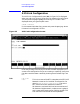
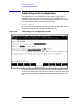
The FDDI Link Configuration screen (#203) in Figure 3-7 is displayed
when you select a link name of type FDDI at the Link Selection screen
(Figure 3-2) and press the
[Add] or [Modify] function key. It is also
displayed when you type the path name:
@LINK.
linkname
in the command window of any screen and press the [Enter] key, where
linkname is the name of a configured FDDI link.
Figure 3-7 FDDI Link Configuration Screen
Press the
[Save Data] function key to transfer the data displayed on the
screen to the configuration file you are creating or updating. Verify that
the data record has been created by checking that the Data flag is set
to Y.
Fields
Physical path of
device adapter The physical path number corresponds to the slot
location of a node’s FDDI device adapter. For HP 3000
systems, the path is derived by a basic formula of
4 x slot number. (Example:4x10=40,where the FDDI
device adapter is installed in slot number 10 and the
physical path of the device adapter is 40.)