
Configuring and Managing Host-Based X.25 Links - Edition 5 (36939-90054)

Chapter 6 125
Configuring X.25 Links Step-by-Step
Modify the Network Management Configuration File
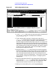
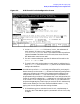
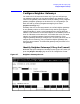
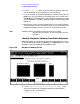
Figure 6-6 X.25 Virtual Circuit Configuration Screen
1. In the Remote node name field, enter, in turn, the nodename of
each remote X.25 node on your network in the format
nodename.domain.organization. Also, if you need to be able to perform a
loopback DSLINE command to the local node, then enter the local
HP 3000 node's name here as well.
2. For each remote nodename, type the IP address of the node in the
Remote IP address field.
3. To specify that calls can be made to a node, enter its address key in
the Address key field. Enter the node portion of the remote node's
configured nodename.
NOTE
An address key called POOL is already preconfigured for you though it
doesn't show up on the screen. POOL allows the node being configured to
receive any incoming calls even if the remote system's address is not
configured on this screen. POOL will also allow you to use NetIPC to
programmatically provide an X.25 address that is not configured on this
screen. If you want to delete the POOL address key, in the last line of the
X.25 Virtual Circuit Configuration screen enter a 3 (for switched VCs)
and press the
[Go To] key. That brings you to the X.25 SVC Address Key
Paths screen where you can then remove the default name POOL by
typing over it with spaces and then saving the data.
4. If the address type is a switched virtual circuit, complete steps a
through c, but if the address type is a permanent virtual circuit, skip
to step 5.