
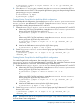
User's Guide
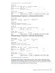

#dev_group ip_address service
dg12 NodeA.dc1.net horcm0 # communicate with DC1 nodes
dg23 NodeC.dc3.net horcm0 # communicate with DC3 nodes
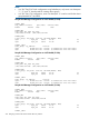
Sample Raid Manager Configuration on a DC3 NodeC (multi-target Bi-Link)
HORCM _MON
#ip_address service poll(10ms) timeout(10ms)
NodeC horcm0 1000 3000
HORCM_CMD
#dev_name dev_name dev_name
/dev/rdsk/c6t2d0 /dev/rdsk/c8t2d0
HORCM_DEV
#dev_group dev_name port# TargetID LU# MU#
dg13 dg13_d0 CL2-A 0 5 h1
#Phantom device group dg23
dg23 dg23_d0 CL2-A 0 5 h2
HORCM _INST
#dev_group ip_address service
dg23 NodeB.dc2.net horcm0 # communicate with DC2 nodes
dg13 NodeA.dc1.net horcm0 # communicate with DC1 nodes
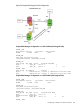
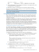
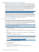
Multi-Hop Bi-Link Raid Manager Configuration
For a Multi-Hop Bi-Link configuration, the DC1, is configured as primary site of an application
and is the source of the data replicating to DC2. The data is then replicated from DC2 to
DC3. A sample Multi-Hop Bi-Link configuration when using 3DC Sync/CAJ replication is as
shown in Figure 79 (page 434). A phantom device group is configured between DC1 and
DC3.
Figure 79 Multi-Hop Bi-Link (1:1:1)
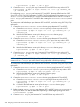
Sample Raid Manager Configuration on a DC1 NodeA (multi-hop-Bi-Link)
HORCM _MON
#ip_address service poll(10ms) timeout(10ms)
NodeA horcm0 1000 3000
HORCM_CMD
#dev_name dev_name dev_name
434 Designing a Three Data Center Disaster Recovery Solution