
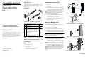
Universal Rack-Mounting Kit

6. Secure the left mounting bracket to the rail-front using two
pan head SEMS screws
4 (10-32 x 5/8 in). See Figure 5.
7. Secure the left mounting bracket to the two side flange
brackets using two pan head SEMS screws
5 (10-32 x 5/8
in). See Figure 5.
8. Install a pan head SEMS screw
6 (10-32 x 1/2 in) at the rear
of the left mounting bracket. See Figure 5.
9. Fully tighten two outer screws
7 located on each side of
mounting bracket’s stop bracket. See Figure 5.
10. Repeat steps 5 through 9 for the right mounting bracket and
then proceed to the “Removing Enclosure Elements” section.
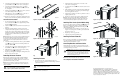
Round Hole Rail Installation
1. For each mounting bracket, remove two alignment clips
from each bracket-front
1 and one alignment clip from the
bracket-rear
2. See Figure 6.
2. Attach U-nut
1 to each of the four inner rails of cabinet (see
Figure 7).
3. Extend the mounting bracket so that the rear studs are
completely inserted through the two rail-rear holes pencil
marked “R.” Swing the left mounting bracket-front directly
behind the left rail-front, aligning the middle two mounting
bracket-front holes with the rail holes pencil-marked “F.”
See Figure 7.
NOTE: For Model 2000 series enclosures, remove pre-installed stop bracket
2, and install the additional stop bracket that shipped with the enclosure.
Be sure the two round, embossed imprints at the top and bottom of the
mounting bracket-front are completely seated inside the correct round
rail-front hole.
4. Secure the mounting bracket-front with two pan head SEMS
screws
3 (10-32 x 5/8 in) and each mounting bracket-rear
stud with a KEP nut 4.
5. Secure the inner side of the mounting bracket using two pan
head SEMS screw
5 (10-32 x 3/4 in). See Figure 7.
6. Fully tighten two screws located on each of the mounting
bracket’s stop bracket
2 (see Figure 7).
7. Repeat steps 3 through 6 for the right mounting bracket and
then proceed to the next section.
Removing Enclosure Elements
Reducing the overall enclosure weight can make installation
easier and safer. Before installing entire enclosure, consider
removing the enclosure’s elements. Refer to the enclosure user
guide for element removal procedures.
NOTE: If enclosure elements are removed, do not stack them. Place each
element on its side, and on a flat, stable, static-free surface, until they are
ready for reinstallation.
WARNING: The enclosure weight with all elements installed,
exceeds 39.5 kg (65 lb). To prevent personal injury, at least two
people are required to install an enclosure safely.
Figure 6: Alignment clip removal
Figure 7: Mounting bracket installation
Figure 8: Enclosure installation
Installing Enclosure
1. Position the enclosure on the mounting brackets (see
Figure 8) and slide it in until the enclosure flanges are flush
against each rail-front.
CAUTION: Hold and slide enclosure in at a 90° angle to prevent
enclosure damage and ease insertion.
IMPORTANT: Once the enclosure is fully inserted, verify that both enclosure
front flanges contact the rack vertical rail.
2. Tighten the captive panel fasteners on each side of the
enclosure-front. See Figure 9.
3. Locate the left side notch
1 on the enclosure at the rear. See
Figure 10.
4. Fully slide left stop bracket on the left mounting bracket into
the enclosure left notch so that the stop bracket fits snugly
inside and against the enclosure.
5. Tighten the stop bracket screw after stop bracket is secured
tightly against enclosure.
6. Repeat steps 3 and 4 for the right stop bracket and notch.
NOTE: The enclosure should not shift forward or backward inside the
mounting brackets after seating it and securing the stop brackets. If the
enclosure shifts significantly, readjust the stop brackets as necessary.
Installing Filler Panels (Select Models Only)
For enclosures shipped with a solid filler panel 1 installed (see
Figure 11), facilitate cable routing to the enclosure-front by
replacing the solid filler panel with the slotted filler panel
2
shipped with the enclosure:
1. Insert the straight-slot screwdriver in one of the slots (see
Figure 11 inset) and pry the solid filler panel outward until
that end becomes loose.
2. Repeat step 1 for the opposite side.
3. Align and snap in the slotted filler panel.
Installing Enclosure Elements
Refer to enclosure documentation for element installation
procedures. Install all enclosure elements removed in the
“Removing Enclosure Elements” section.
Connecting Data Bus and Power Cables
All data bus and power cables are connected at the rear of the
enclosure. Refer to enclosure documentation for information on
connecting data and power cables.
CAUTION: Circuitry operations for enclosures without a power
ON/OFF switch will begin once power cable is connected. For these
enclosures, connect power cables after all data bus cables are
connected. Failure to connect all cabling properly prior to power
activation may damage the enclosure.
NOTE: Route cabling in a way that allows easy removal of enclosure elements.
This completes the hardware installation.
Figure 9: Captive screw fasteners
Figure 10: Enclosure notch and stop bracket
Figure 11: Filler panel replacement
For additional information, visit our website at:
http://www.compaq.com. Or in North America, call Compaq
technical support at 1-800-OK-COMPAQ. Outside North
America, call Compaq technical support at the nearest location.
Telephone numbers for worldwide technical support are listed on
the Compaq website. For continuous quality improvement, calls
may be recorded or monitored.
1
2
CXO7625A
CXO7630A
1
2
5
4
5
3
CXO7631A
CXO7633A
CXO7632A
1
CXO7634A
1
2