
HSG80 ACS Solution Software Version 8.7 for Compaq Tru64 UNIX Installation and Configuration Guide
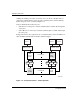
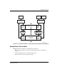
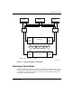
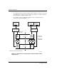
Table Of Contents
- HSG80 ACS Solution Software Version 8.7 for Compaq Tru64 UNIX Installation and Configuration Guide
- About this Guide
- 1- Planning a Subsystem
- Defining Subsystems
- What is Failover Mode?
- Selecting a Cache Mode
- Enabling Mirrored Caching
- What is the Command Console LUN?
- Determining Connections
- Assigning Unit Numbers
- What is Selective Storage Presentation?
- 2- Planning Storage Configurations
- Where to Start
- Determining Storage Requirements
- Configuration Rules for the Controller
- Addressing Conventions for Device PTL
- Choosing a Container Type
- Creating a Storageset Profile
- Planning Considerations for Storageset
- Changing Characteristics through Switches
- Specifying Storageset and Partition Switches
- Specifying Initialization Switches
- Specifying Unit Switches
- Creating Storage Maps
- 3- Preparing the Host System
- Installing RAID Array Storage System
- Making a Physical Connection
- Preparing LUNs for Access by Tru64 UNIX FileSystem
- DECsafe Available Server Environment (ASE)
- HSG80 Units and Tru64 UNIX Utilities
- Solution Software Upgrade Procedures
- New Features, ACS 8.7 for Tru64
- 4- Installing and Configuring HSG Agent
- 5- FC Configuration Procedures
- Establishing a Local Connection
- Setting Up a Single Controller
- Setting Up a Controller Pair
- Configuring Devices
- Configuring Storage Containers
- Assigning Unit Numbers and Unit Qualifiers
- Configuration Options
- Verifying Storage Configuration from Host
- 6- Using CLI for Configuration
- 7- Backing Up, Cloning, and Moving Data
- A- Subsystem Profile Templates
- Storageset Profile
- Storage Map Template 1 for the BA370 Enclosure
- Storage Map Template 2 for the second BA370 Enclosure
- Storage Map Template 3 for the third BA370 Enclosure
- Storage Map Template 4 for the Model 4214R Disk Enclosure
- Storage Map Template 5 for the Model 4254 Disk Enclosure
- Storage Map Template 6 for the Model 4310R Disk Enclosure
- Storage Map Template 7 for the Model 4350R Disk Enclosure
- Storage Map Template 8 for the Model 4314R Disk Enclosure
- Storage Map Template 9 for the Model 4354R Disk Enclosure
- B- Installing, Configuring, and Removing the Client
- C- SWCC Agent in TruCluster Environment
- SWCC Overview
- Running the SWCC Agent on a V4.0G Cluster
- Running the SWCC Agent under ASE Services
- Running the SWCC Agent on a V5.x Cluster
- Problems with Running the Agent on Multiple Clusters
- Configure the Controller
- Use Multiple-Bus Failover Mode
- Verify That the HSG80/HSG60 Unit Offsets Are Zero
- Install and Run the Agent on One Cluster Member
- Example of Installing the Agent on a Cluster Member
- Create the CAA Action Script
- Create the CAA Resource
- Glossary
- Index

Planning a Subsystem
1–13HSG80 ACS Solution Software Version 8.7 for Compaq Tru64 UNIX Installation and
Configuration Guide
1–13
Determining Connections
The term “connection” applies to every path between a Fibre Channel adapter in a host
computer and an active host port on a controller.
NOTE: In ACS Version 8.7, the maximum number of supported connections is 96.
Naming Connections
It is highly recommended that you assign names to connections that have meaning in
the context of your particular configuration. One system that works well is to name
each connection after its host, its adapter, its controller, and its controller host port, as
follows:
Examples:
A connection from the first adapter in the host named RED that goes to port 1 of
controller A would be called RED1A1.
A connection from the third adapter in host GREEN that goes to port 2 of controller B
would be called GREEN3B2.
NOTE: Connection names can have a maximum of 9 characters.
Numbers of Connections
The number of connections resulting from cabling one adapter into a switch or hub
depends on failover mode and how many links the configuration has:
• If a controller pair is in transparent failover mode and the port 1 link is separate
from the port 2 link (that is, ports 1 of both controllers are on one loop or fabric,
and port 2 of both controllers are on another), each adapter will have one
connection, as shown in Figure 1–9.
HOST1A1
HOST
NAME
PORT
CONTROLLER
ADAPTER