HP Virtual Connect Enterprise Manager 7.3 User Guide Abstract This document is intended to be used by technical professionals who manage multiple HP BladeSystem enclosures and use HP Virtual Connect Manager to control network connectivity. HP assumes that you have installed Virtual Connect, are familiar with the embedded VCM web console, and have read the HP Virtual Connect for c-Class BladeSystem User Guide and understand its concepts.
© Copyright 2007, 2014 Hewlett-Packard Development Company, L.P. Confidential computer software. Valid license from HP required for possession, use or copying. Consistent with FAR 12.211 and 12.212, Commercial Computer Software, Computer Software Documentation, and Technical Data for Commercial Items are licensed to the U.S. Government under vendor's standard commercial license. The information contained herein is subject to change without notice.
Contents 1 Introduction...............................................................................................9 Key features and benefits...........................................................................................................9 Key features........................................................................................................................9 Key benefits................................................................................................................
Removing a VC Domain from a VC Domain Group.....................................................................52 Working with multienclosure VC Domains..................................................................................53 VC Domain Maintenance........................................................................................................56 Replicating VC Domain Group configurations to other VC Domains during VC Domain Maintenance.......................................................
Moving Ethernet networks (VLANs tagged) from one shared uplink to another................................95 Correlating VCEM operations in Systems Insight Manager and VC logs.........................................95 5 Managing server profiles...........................................................................96 Creating a server profile........................................................................................................100 Concealing unused FlexNICS .............................
Transferring all managed VC Domains from one VCEM instance to another.............................140 Transferring one managed VC Domain from one VCEM instance to another............................141 Consolidating multiple VCEM instances into a single VCEM instance .....................................142 Displaying factory default MAC and WWN addresses.........................................................143 Deleting WWN exclusion ranges.................................................................
VCM shows an incorrect address for VCEM.............................................................................164 Communicating with the enclosure OA....................................................................................164 MAC, WWN, and Serial Number management.......................................................................165 Duplicate MAC and WWN address assignments.....................................................................
14 Support and other resources...................................................................181 Information to collect before contacting HP...............................................................................181 How to contact HP................................................................................................................181 Security bulletin and alert policy for non-HP owned software components....................................181 Subscription service.....................
1 Introduction VCEM centralizes network connection management and workload mobility for HP BladeSystem servers that use Virtual Connect to access LANs, SANs, and converged network environments. VCEM helps organizations increase productivity, respond faster to workload and infrastructure changes, and reduce operating costs.
• Group-based management of Virtual Connect Domains increases infrastructure consistency, simplifies system deployment and enables rapid change management across hundreds of HP BladeSystem enclosures. • Add, change, and failover servers and their workloads across the data center in minutes without impacting production networks. • Increase productivity and server-to-administrator ratios. • Release LAN and SAN administrators from routine server-centric tasks.
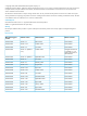
Table 1 (page 11) lists all available VCEM licenses, including Virtual Connect hardware and VCEM packaged options.
that LANs and SANs see NIC or HBA addresses presented by the VC modules instead of the default burned-in interface addresses. VC provides several key advantages: • Reduces physical server-to-network cabling, complexity, and leased network ports. • Maintains constant end-to-end connections to preferred networks and fabrics. • Enables administrators to wire LAN and SAN connections once and limit changes.
To establish server connections to LANs and SANs, VC uses server connection profiles in combination with dynamic pools of unique media access control (MAC) addresses and world wide names (WWN). A VC server profile is a logical grouping of server connection attributes that can be assigned to any bay in a BladeSystem enclosure.
a physical stand-alone console, as a plug-in to Systems Insight Manager, and as a virtual server guest. The majority of VCEM operations are accessed through a dedicated home page which includes the following core tasks: • Discover and import existing VC Domains without system downtime. • Aggregates individual VC address information for LAN and SAN connectivity into a centrally administered VCEM address repository. • Create VC Domain Groups. • Assign and unassign VC Domains to VC Domain Groups.
Figure 3 VCEM architecture overview Using VCEM, system administrators can quickly deploy, replace and recover servers and their associated workloads by assigning or reassigning the VC server connection profile to an enclosure bay. The example in Figure 4 (page 16) illustrates a server profile movement operation from “Server A” to “Server C” using VCEM.
Figure 4 VC server profile movement example 16 Introduction
2 Installing and configuring VCEM This chapter describes how to install and configure VCEM. IMPORTANT: This guide assumes that you have previously configured VC using the integrated VCM, have read the HP Virtual Connect for c-Class BladeSystem User Guide, and understand its concepts.
Figure 5 VC Domain compatibility support In each case, the newer versions of VC will behave functionally like the oldest version of firmware running on any VC Domain in the VC Domain Group. No features beyond those that are supported by the oldest version of VC firmware in the VC Domain Group can be enabled on any of the VC Domains in the VC Domain Group even if they are running a newer version of VC firmware.
join the VC Domain Group if it has any features enabled beyond the features supported by the group firmware mode. Table 4 illustrates how the group firmware mode is determined based on the versions of VC firmware installed on the VC Domains in the VC Domain Group. Table 4 Determining group firmware mode VC Domain Group name Domain A Domain B Domain C Domain D Group firmware mode GroupOne 3.18 3.30 3.30 3.60 3.15 GroupTwo 3.30 3.5x 3.60 3.7x 3.3x GroupThree 3.60 3.7x 4.0x 4.1x 3.
If you are upgrading your CMS and have VCEM 6.2 to 7.0 running on a 64-bit operating system, you can directly update installations with the HP Insight Management DVD. Figure 6 (page 20) shows the 32-bit to 64-bit operating system update path. Figure 6 Update path IMPORTANT: VCEM 7.3 does not support VC firmware versions prior to VC 3.30. If you have versions of VC firmware before 3.
You must upgrade the VC Domain firmware and the VC Domain Group firmware mode to 3.3x or later before you can manage those VC Domains and VC Domain Groups with VCEM 7.3. Table 7 displays VC Domain Group firmware compatibility. Table 7 VC Domain Group firmware compatibility VC firmware VC Domain Group VC Domain Group VC Domain firmware mode firmware mode Group firmware 4.1x 4.0x mode 3.7x VC Domain Group VC Domain Group firmware mode firmware mode 3.5x 3.3x 4.1x Yes Yes Yes Yes yes 4.
Table 8 VCEM ports (continued) CMS Managed System Port Protocol1 Description configuration backup from CLI Y 636 TCP LDAP Authentication Y 514 UDP SYSLOG Y 1812, 1813 UDP RADIUS server if configured Y 49 TCP TACACS server if configured 1 All ports are used for TCP and UDP. 2 The CMS normally has all managed system ports open, as the CMS is a managed system itself. Firewalls can be configured to block these ports if the CMS is not to be managed from another system.
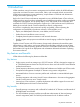
1. Select the VC Domains that are targeted for firmware updates. NOTE: Using the firmware update workflow requires VCSU 1.8.0 or later and the VC Domains being updated must be running VC 3.50 or later. Otherwise, enable maintenance mode on the VC Domain in preparation for updating the VC firmware with VCSU. Figure 7 VC Domain tab page 2. 3. Select VC Domain Firmware Update... and all the VC Domains selected are displayed. Select Enable Firmware Update... (Figure 8).
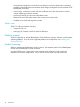
Figure 9 Firmware update message After the job completes, use the VCSU to perform the firmware update and then proceed to Step 4. 4. Check mark the targeted VC Domains on the VC Domain tab and select VC Domain Firmware Update... again. NOTE: If another VC Domain with a status other than Firmware update is selected, the VC Domain Firmware update button is disabled. 5. Select Complete Firmware update to finish the firmware update process (Figure 10).
If you are running firmware with the HP 1/10Gb VC-Enet module or the HP 1/10Gb-F VC-Enet module you will need to replace those with one of the following modules to update to VC firmware 3.7x or later: • HP VC Flex-10 Enet Module • HP VC FlexFabric 10Gb/24-Port Module • HP VC Flex-10/10D Module For information on replacing modules, see “Replacing VC modules” (page 175). Updating to VC firmware 4.1x The HP 4Gb VC-FC module is not supported by VC firmware versions 4.1x and later.
2. Choose one of the following options: • Select Start→ All Programs→HP Virtual Connect Enterprise Manager→HP Virtual Connect Enterprise Manager • Select HP SIM→Tools→ Integrated Consoles→ Virtual Connect Enterprise Manager (VCEM) If VCEM is a stand-alone installation, click the VCEM desktop icon. The VCEM home page appears. 3. Enter the credentials that you entered when performing the installation. The VCEM home page appears.
NOTE: Creating exclusion ranges is optional but highly recommended to avoid MAC/WWN address conflicts in the same network. HP recommends using exclusion ranges in the following scenarios: • When VC Domains are not VCEM controlled and are using other user-defined MAC or WWN addresses that overlap with VCEM user-defined MAC or WWN ranges. For example: VCEM exclusion ranges need to be created for MAC or WWN addresses used by other VC Domains. • When installing multiple instances of VCEM in the same network.
11. Create a new VC Domain Group, and then add one or more already-licensed VC Domains to it. For more information on creating a new VC Domain Group, see “Creating a VC Domain Group” (page 43). IMPORTANT: In a new environment, when adding VC Domains to into the VC Domain Group, you must have one configured VC Domain. Any additional VC Domains can remain nonconfigured as they are automatically configured by VCEM.
In the event of an unplanned failover, it is possible that manual intervention may be required to restore full operations. If a VC Domain reports configuration mismatch or an out-of-sync occurrence after recovering from an unplanned failover, the following actions are recommended. • Execute Mxsync in analysis mode (mysync) to determine the nature of the failure on the VC Domain during the CMS recovery phase.
3 Managing VC Domains This chapter describes how to use VCEM to manage VC Domains. On the VC Domains page, you can filter the VC Domain list by VC Domain Group. The default filter shows all VC Domains. Figure 11 VC Domains window Table 9 (page 30) lists the columns on the VC Domains page.
Table 10 VCEM status icons (continued) Status Icon Description Missing external manager lock/Communication established with disabled enclosure VCEM is unable to obtain the necessary permissions for External Manager user. VCEM might have lost the External Manager lock at the VC Domain. Expired license The VC Domain enclosure has an expired license. Managed by VCEM The VC Domain is part of a VC Domain Group and operating normally.
minimum number of enclosures. For more information about multienclosure VC Domains, see “Working with multienclosure VC Domains” (page 53). • VC Domain names must not already exist in VCEM. • Server profile names must not already exist in VCEM. • MAC or WWN addresses or serial numbers that are assigned to a server profile must not be in use by VCEM or in a VCEM exclusion list.
VCEM validates the following components when adding a VC Domain to a VC Domain group, therefore the VC Domain configuration must be identical to the VC Domain Group configuration.
• 34 For each single network uplink: ◦ Network name ◦ Smart link ◦ Private Network ◦ Enable VLAN Tunneling ◦ State ◦ Network port location ◦ Speed/duplex mode ◦ Connection mode ◦ Preferred Link Connection ◦ Preferred Link Connection Speed ◦ Maximum Link Connection ◦ Maximum Link Connection Speed ◦ Network Access Groups (associated with this network) • Number of networks configured in the VC Domain • For each shared network uplink: ◦ Uplink set name ◦ Network port location
• • ◦ Maximum Link Connection Speed ◦ Network Access Groups (associated with this network) For each Fibre Channel SAN Fabric: ◦ Fabric name ◦ Fabric port location ◦ Configuration speed Number of Fibre Channel SAN Fabrics configured in the VC Domain To add an unconfigured VC Module to a VC Domain Group, the following items must be identical: • Interconnect bays location and model • Enclosure model • Uplinks of the network and Fibre Channel SAN Fabric • Power state of the VC Modules VC 4
Figure 13 SNMP access and trap destinations To disable this feature, delete all the items in the SNMP access and trap destinations tables that are configured to use IPv6 addresses. VC 4.0x features that must be disabled in a VC Domain to be part of a VC Domain Group with VC firmware 3.7 The following features are not supported: • Dual-Hop FCoE Do not configure VC Domains with FCoE networks or server profiles with FCoE connections linked to Flex-10/10D modules.
from FCoE to Ethernet. Also update the server profiles by removing the FCoE connections that are linked to Flex-10/10D modules. • LACP timers Do not configure LACP timers in VC Domains, Uplink Sets, or networks with a Long (30 sec) value.
Figure 16 Ethernet Network LACP timer configuration Figure 17 Uplink Set LACP timer configuration To disable this feature: 1. Change the VC Domain LACP timers from Long (30 sec) to Short (1 sec). 2. Change each network and uplink set configuration from Long (30 sec) to Domain Default,Short (1 sec) or Short (1 sec) • IGMP Multicast Filter Sets or Multicast filters Do not configure IGMP Multicast Filter Sets or Multicast filters in VC Domains.
Figure 18 Server profile configured with IGMP Multicast Filter Set or Multicast filter Figure 19 VC Domain configured with a IGMP Multicast Filter Set Figure 20 VC Domain configured with IGMP Multicast filter Requirements for adding a VC Domain to a VC Domain Group 39
To disable this feature, it is necessary to first remove the Multicast Filter Sets and then remove the Multicast filters. 1. Remove the association between server profile Ethernet connections and Multicast Filter Sets or Multicast filters by selecting None in the Multicast Filter column (see Figure 18) . 2. Remove the Multicast Filter Sets and then remove the Multicast filters (see Figure 19, and Figure 20).
Figure 23 SAN fabrics with direct attach fabric type To disable this feature delete all direct attach SAN fabrics. • The SNMP access feature is not supported. To disable this feature delete all the items on the SNMP access table. See Figure 24 (page 41) for more information. Figure 24 SNMP access configuration VC 3.7x, 3.6x and 3.5x features that must be disabled in a VC Domain to be part of a VC Domain Group with VC firmware 3.3x All VC 3.5x, 3.6x, and 3.
for C3000 enclosures only) in the “Connected To” column. See Figure 25 (page 42) for more information. Figure 25 Removing FC and FCoE connections in 3.5x To disable this feature, delete the additional FC SAN connections or FCoE connections (that exceeds the 4 redundant connections to each Virtual Connect Fibre Channel/Virtual Connect FlexFabric Module) from the server profile. VC Domain tasks From the VC Domains page, you can perform the following tasks: • License an enclosure.
2. 3. 4. 5. Click Add Key and enter the key string. Select one or more unlicensed VC Domains. Click Apply License. Click OK to validate the key string. NOTE: License key fields are case-sensitive If the key string is valid, the key is added to HP Insight Management. 6. • Click Next to provide VC Domain credentials. For existing VC Domain Groups: 1. Select the VC Domain from the VC Domains page, and then click License. The License Enclosure page appears. 2. 3. Click Add Key.
3. 4. 5. Skip the Network and Fibre Channel configuration wizards, and then navigate directly to the VC Domain user interface. From VCM, find and import the necessary remote enclosures in the correct order. For more information on remote enclosures, see the HP Virtual Connect for c-Class BladeSystem Setup and Installation Guide. From Systems Insight Manager, perform a manual discovery of the Onboard Administrator IP address for all related VC Domain enclosures.
4. Enter the VC Domain Group name in the VC Domain Group Name field. Valid VC Domain Group names can contain alphanumeric characters, hyphens (-), dot (.), and underscores (_), and cannot exceed 64 characters. 5. From the Configuration based on VC Domain list, select the VC Domain configuration on which the new VC Domain Group will be based. The Configuration VC Domain list contains only configured VC Domains. 6.
NOTE: • Create the VC Domain Groups, then define VCEM access to authorized users. • By default the OS administrator user account has VCEM administrator rights to all VCEM VC Domain Groups. • A user account can be associated with different VC Domain Groups and have different privileges for each of the groups. Likewise, a VC Domain Group can have different users associated with it who have different privilege levels.
Figure 26 Systems Insight Manager Users and Authorizations page 7. Under Select Toolbox(es) select the VCEM role you want to use to restrict access (for example, "VCEM Domain Group Administrator"). See Figure 26 for more information.
8. Under Select Systems: a. CMS type roles: If you want these roles to apply to all VCEM pages, then select CMS. b. Group type roles: Select Add, the select the VCEM VC Domain Group for which you want to restrict access (for example, "vcdg-1") and click Apply. The selected VCEM VC Domain Group will appear automatically in Select Toolbox(es). See Figure 27 for more information.
Table 13 VCEM operations and RBAC privileges (continued) VCEM operations VCEM or VCEM roles administrator VCEM group administrator VCEM group operator VCEM group limited operator VCEM user (Read-only) List VC Domains x x x x x List VC Domain Groups x x x x x Display profile details x x x x x Display bay details x x x x x Display job details x x x x x Display VC Domain Group details x x x x x Display VC Domain details x x x x x Delete job x N N N N Failove
Table 13 VCEM operations and RBAC privileges (continued) VCEM operations VCEM or VCEM roles administrator VCEM group administrator VCEM group operator VCEM group limited operator VCEM user (Read-only) Delete VC Domain Group x x N N N Upgrade VC Domain Group firmware mode x x N N N Update VC x Domain firmware x N N N License Enclosure x N N N N Change server power state x x x N x Adding a VC Domain to a VC Domain Group Select Add to VCD Group to add a VC Domain to a VC Domain
The FC module can become incompatible in the following situations: • An HP Virtual Connect 4 Gb FC module replaces an HP Virtual Connect 8 Gb 24-port FC module. • An HP Virtual Connect 8 Gb 24-port FC module replaces a HP Virtual Connect 4 Gb FC module. • HP Virtual Connect 8 Gb 24-port FC modules and HP Virtual Connect 4 Gb FC modules share the same I/O bay slice (for example, an HP Virtual Connect 4 Gb FC module in I/O Bay 3, and an HP Virtual Connect 8 Gb 24-port FC module in I/O Bay 4.).
1. 2. 3. 4. Export the server profiles from the VC Domain to the target VC Domain Group (and leave the server profiles unassigned). The VCEM export operation will match all resources in use by server profile and change the necessary elements to allow the migration to complete. Select Overwrite Configuration to add the VC Domain to the target VC Domain Group. VCEM overwrites the VC Domain with the VC Domain’s configuration.
3. Perform the following steps for each VC Domain that uses HP-predefined or user-defined ranges that you want to remove from the VC Domain Group. NOTE: Factory-default MAC, WWN, and serial number ranges are released to VCM as factory-default. If factory-default MAC or WWN addresses or serial numbers are not being used, you must specify address ranges for each removed VC Domain. These address ranges must be unique to avoid assignment of duplicate addresses.
See “Related information” (page 182) for documents that can have more information on “stacking links.” Figure 28 (page 54) illustrates a valid configuration of Ethernet and Fibre Channel Virtual Connect modules in a VC Domain with multiple enclosures. The black lines linking the Ethernet modules illustrate the stacking links.
Figure 29 VC Domain Group with VC Domains that have different numbers of enclosures A multienclosure domain can only be configured as follows: • The enclosure must be a c7000 enclosure. • See the VC documentation available at: http://www.hp.com/go/vc for details on which Virtual Connect Ethernet modules are supported for primary and secondary roles for the VC firmware revision in your environment. • FC modules in every enclosure must match the model and disposition.
For more information, see the HP Virtual Connect Manager documentation. VC Domain Maintenance VC Domain Maintenance is a useful way to perform updates on a particular VC Domain without removing it from a VC Domain Group, and apply the common domain, network and storage configuration changes automatically to all other VC Domains that belong to the same VC Domain Group. VCEM accomplishes this task by temporarily enabling domain, network, and storage changes through the local VCM for the selected domain.
• Setting SSL Certificate • Ethernet Settings: ◦ MAC Cache failover ◦ IGMP Snooping ◦ Multiple Networks Link Speed Settings ◦ Server VLAN Tagging Support • Shared Uplink Set • Resetting VC module (soft reset) • Monitoring network ports • Configuring networks • Configuring storage • Login Banner Configuration • Enclosures Configuration: ◦ Find ◦ Import ◦ Delete • Storage Management Credentials • SNMP Configuration • Network Access Groups • Link Stability Redistribution
Replicating VC Domain Group configurations to other VC Domains during VC Domain Maintenance IMPORTANT: The VC Domain, network, and storage configuration changes performed during VC Domain Maintenance are automatically replicated to all other VC Domains that belong to the same VC Domain Group when the VC Domain maintenance operation is completed. The configuration changes are rolled back for the domain and not replicated to other domains if the maintenance operation is cancelled instead of completed.
◦ ◦ Multiple Network Speed Settings: – Preferred Link Connection – Preferred Link Connection Speed – Maximum Link Connection – Maximum Link Connection Speed Network SNMP settings: – Enable SNMP – Read Community – System Contact – Each SNMP trap defined community and IP address – SNMP Security Enhancements ◦ Port Throughput statistics ◦ Port throughput statistics configuration information ◦ Network Loop Protection ◦ VLAN Capacity – • • Fibre Channel SAN fabric settings: ◦ Enab
• • ◦ Connection mode ◦ Preferred link connection ◦ Preferred link connection speed ◦ Maximum link connection ◦ Maximum link connection speed ◦ Network Access Groups (associated with this network) ◦ Colors ◦ Labels For each shared network: ◦ Uplink Set Name ◦ State ◦ Smart Link ◦ External VLAN ID ◦ Native VLAN ◦ Number of VLANs tagged associated with the shared network uplinks ◦ Network Access Groups (associated with this network) ◦ Colors ◦ Labels For each uplink set na
NOTE: When a VC Domain has a status of Under maintenance, VCEM does not allow you to perform server profile operations in any VC Domains which belong to that VC Domain Group. This restriction also precludes any operation permissions delegated to the server role as a result of VCM role operation configuration customizations. You can have a maximum of one VC Domain in the VC Domain Group that has a status of Under maintenance. 3. Confirm the VC Domain changes through VCEM.
4. 5. 6. 7. To unlock VCM for domain, network, and storage changes, click Make changes via VC Manager. The VCM web interface appears in a separate browser window. The Under Maintenance status indicates that the VC Domain is temporarily unlocked for domain, network, and storage changes. Using VCM: a. Log in to VCM with the required user rights. b. Perform the domain restoration by selecting Domain Settings→Domain Configuration, and selecting the Backup/Restore tab. c. Click Backup configuration.
Changes in VCM that might cause problems in completing VC Domain Maintenance include: • Updating the VC firmware to an incompatible version, (Domain Settings→Firmware Management). To resolve this issue, update the VC firmware version to a compatible version and complete VC Domain Maintenance again. • Deleting the domain (Domain Settings→Domain Configuration). To resolve this issue, restore the VC configuration from a backup, or remove the VC Domain from the VC Domain Group.
NOTE: QoS settings are only displayed in both the VC Domain and VC Domain Group details in VCEM. For more information on configuring QoS see the HP Virtual Connect for c-Class BladeSystem User Guide at http://h18004.www1.hp.com/products/ blades/components/c-class-tech-installing.
Figure 34 QoS custom without FCoE lossless configuration type VC Domain Maintenance 65
Figure 35 QoS custom without FCoE lossless (DOT1P mapping) configuration type Viewing VC Domain and VC Domain Group roles To view allowed VC Domain role permissions perform the following steps: 1. Select the VC Domain tab from the home page. 2. Click the target VC Domain.
3. Select the Operation Permissions tab to view VC Domain roles. Figure 36 displays an example. Figure 36 VC Domain operation permissions tab NOTE: Operation permissions are only displayed in VCEM. For more information on VCM customizing role permissions see the HP Virtual Connect for c-Class BladeSystem User Guide at http://h18004.www1.hp.com/products/blades/components/c-class-tech-installing.html.
Statistical throughput attributes VCEM displays statistical-throughput configuration information in the VC Domain Properties and the VC Domain Group properties windows including: • Add to Group—When a VC Domain is added to a VC Domain Group, the statistics-throughput configuration setting from the VC Domain Group is applied to the VC Domain.
Optimized bandwidth types are displayed in the VC Domain properties page and Allocated port speed (min-max) entry has been added to the Ethernet, Flex -10 iSCSI and FCoE connections screens. Figure 39 displays an FCoE connections screen example. Figure 39 FCoE allocated port speed example You can also view or select a new value for the FCoE connections table preferred port speed on the edit server profile page.
Figure 42 VC Domain network details LACP timer attributes SNMP Access VCEM displays VC Domain and VC Domain Group Ethernet SNMP access information by clicking More Details ... at the bottom of the properties window. Figure 43 and Figure 44 displays SNMP access. NOTE: This feature is only available for Ethernet modules and not available on VC firmware earlier than 3.7x.
Figure 44 Displaying Ethernet SNMP access for IPv6 Viewing IPv6 addresses of managed VC Domains Figure 45 displays a managed VC Domain IPv6 address. NOTE: This feature is only available with VC firmware 4.1x or later.
Using VLAN capacity CAUTION: VCM firmware versions 3.3x through 3.6x or later does not allow you to easily revert back from Expanded VLAN capacity mode to Legacy capacity mode. To revert back to Legacy capacity mode, you must delete the VC Domain in VCM. VC firmware 3.7x removes support for legacy VLAN capacity. All VC domains with VC 3.7x installed support "Expanded VLAN Capacity". When adding a VC 3.
Canceling a VC Domain Maintenance task Canceling a VC Domain Maintenance discards domain, network, and storage configuration changes that you have performed while in maintenance mode, and returns the VC Domain to the configuration that is shared by all VC Domains within a VC Domain Group. If the VC firmware on the VC Domain is updated while the domain is in maintenance mode, the updated firmware is not rolled back if maintenance is canceled.
Figure 46 Job details Replacing the HP 1/10 Gb VC-Enet or the HP 1/10 Gb-Enet modules To upgrade the HP 1/10 Gb VC-Enet module or the HP 1/10 Gb-Enet module to use the HP VC Flex-10/10D module see sections “Replacing VC Ethernet modules with FlexFabric modules in an existing VCEM managed VC Domain” (page 75) or “Replacing VC Ethernet in interconnect bays three to eight with FlexFabric in an existing VCEM managed VC Domain” (page 75).
6. Perform the first four steps again for each managed VC Domain that you want to add the HP Virtual Connect FlexFabric 10 Gb/24port module to and add the VC Domain to the new VC Domain Group. After performing all the steps in “Adding FlexFabric modules to an existing VCEM managed VC Domain” (page 74), you can create or edit any existing server profiles and use the available networks or SAN Fabrics from the FlexFabric module to create FCoE or iSCSI connections.
7. 8. 9. 10. 11. 12. 13. 14. Add the two FlexFabric modules in both horizontally adjacent bays three and four. Create new Ethernet network connections and FC SAN Fabrics connections linked to the FlexFabric module uplink ports. Create a new VC Domain Group with the latest version of firmware in VCEM using this VC Domain (with the HP Virtual Connect FlexFabric 10 Gb/24port module).
4. 5. 6. 7. 8. 9. 10. 11. 12. 13. Unassign any Flex-10 NICs with profile connections that are attached to the interconnect bays being upgraded. This can be done by unassigning the Ethernet connections in the server profile. HP recommends that you do this in order so you do not lose the MAC addresses. Delete any existing Ethernet network connections that were created using uplinks from the interconnect bays that are to be replaced.
IMPORTANT: After installing the new VC FC modules, omit any VC steps to recreate FC connections. You must use VCEM to recreate and reassign server profile connections. 5. 6. 7. Click the VC Domains tab from the VCEM home page. Select the same VC Domain and click Add to VC Domain Group if there is an existing VC Domain Group that meets the minimum requirements. Otherwise, click New VC Domain Group. Wait for the job to complete successfully.
3. 4. Click Remove from VC Domain Group. Wait for the job to complete successfully. Follow the steps described in the HP Virtual Connect for c-Class BladeSystem User Guide at http://h18004.www1.hp.com/products/blades/components/c-class-tech-installing.html for your specific replacement scenario. CAUTION: If a VC firmware update is required for the scenarios below then make sure that you select a VC firmware version supported by the VCEM version.
8. If you kept the server profiles (step 1) unassigned in the VC Domain Group then perform the following steps to assign the server profiles back to the original VC Domain with replaced VC modules: a. Click the Server Profiles tab from the VCEM home page. b. Select VC Domain in the first filter and select the VC Domain name (with the replaced VC modules) in the second filter. c. For each server profile that was in the VC Domain (now with replaced VC modules) perform the following steps: i.
8. Recreate the server profile SAN connections in VCEM. CAUTION: The VC and VCEM identifiers (WWNs) associated with the removed server profiles’ FC connections can be assigned to different server ports or slots in the recreated server profile SAN connections using FCoE Connections. Recreating the SAN connections in the server profile means that the newly created connections will be assigned new WWNs. 1.
4 Managing VC Domain groups This section describes the management of VC Domain Groups using VCEM. A VC Domain consists of an HP BladeSystem enclosure, a set of associated Virtual Connect Ethernet and Fibre Channel interconnect modules, and server blades that are managed together by a single instance of VCM. The VC Domain contains specified networks, server profiles, and user accounts that simplify the setup and administration of server connections.
Table 15 Group icons and status Status Icon Description Configuration in synch All VC Domains that belong to this VC Domain Group share the same domain configuration Under maintenance VC Domain is unlocked for domain, network, and storage changes through the VCM. After completing the domain, network and storage changes, you must confirm the new VC Domain configuration in VCEM.
4. 5. From VCM, find and import the necessary remote enclosures in the correct order. For more information on remote enclosures, see the HP Virtual Connect for c-Class BladeSystem Setup and Installation Guide. Go to Systems Insight Manager and perform a manual discovery on Onboard Administrator IP address of all related VC Domain enclosures. If you are using the HP VC FlexFabric 10 Gb 24-port module, ensure that the module status is compatible. If the module is incompatible, an error message appears.
10. From the Select WWN range type list, select whether the WWN address range type is VCEM-defined, user-defined, or factory-default. You can only select the user-defined option for WWN range type if a WWN custom range is defined. 11. Click OK. The Virtual Connect Enterprise Manager is executing the request message appears. 12. Click OK to go to the Jobs page and monitor job progress. 13.
be upgraded to [{1}]. Do you want to upgrade the VC Domain Group firmware mode? Click 'Yes' to upgrade the VC Domain Group firmware mode in addition to completing the VC Domain Maintenance operation. Or click 'No' if you want to complete VC Domain Maintenance operation at this time. You can manually upgrade the VC Domain Group firmware mode at a later time by selecting 'Upgrade Firmware Mode' on the VC Domain Groups page. • 8. Click Cancel to discard the VC Domain configuration changes.
IMPORTANT: the Upgrade Firmware Mode feature is used to control what firmware level will be used for the VC Domain Group as a whole. For example, if the FW mode of the VC Domain Group is 3.30, then the base VC Domain configuration data and profile operations will all behave as though they contain VC FW 3.30.
4. Perform the following actions for each VC Domain that uses HP-predefined or user-defined ranges within the VC Domain Group that you want to remove. Factory-default MAC and WWN ranges are released back to VCM as Factory-default. If factory-default MAC or WWN addresses or serial numbers are not being used, address ranges must be specified for each removed VC Domain. These address ranges must be unique and distinct to prevent assignment of duplicate addresses.
NOTE: For QoS, Operation Permissions and multicast filters, details are only available if the VC Firmware is 4.0x or later. Figure 48 VC Domain Group details page Select a detail tab and view all properties about that tab. Figure 49 displays the VC Domain Group tab. Figure 49 VC Domain Group properties tab Viewing VC Domain Group QoS details To view QoS information on the VC Domain Group details page, select the QoS tab and the appropriate OoS is displayed.
NOTE: the QoS settings are only displayed in VCEM. For more information on configuring QoS see HP Virtual Connect for c-Class BladeSystem User Guide at http://h18004.www1.hp.com/products/ blades/components/c-class-tech-installing.
Figure 52 QoS custom without FCoE lossless configuration type Displaying VC Domain Group detail tabs 91
Figure 53 QoS custom without FCoE lossless (DOT1P mapping) configuration type Viewing VC Domain Group roles To view allowed VC Domain Group role permissions, perform the following steps: 1. Select the VC Domain Group tab from the home page. 2. Click on the target VC Domain Group. 3. Select the Operation Permissions tab to view VC Domain Group roles. Figure 54 (page 92) displays an example. NOTE: Operation permissions are only displayed in VCEM and do not affect the VCEM GUI.
Figure 55 VC Domain Group multicast filters Statistical throughput attributes VCEM displays statistical throughput configuration information in the VC Domain Properties and the VC Domain Group properties windows including: • Add to Group—When a VC Domain is added to a VC Domain Group, the statistics-throughput configuration setting from the VC Domain Group is applied to the VC Domain.
Figure 57 VC Domain Group details for Converged Uplink sets and FCoE networks Viewing LACP timer attributes for VC Domain Groups VCM offers you the option of configuring the timeout for LACP which changes the frequency of control messages (LACPDU). The feature allows you to change the frequency, which can be either a short duration (1 second) or a long duration (30 seconds). Figure 58 displays default LACP timer duration information in the VC Domain Group properties.
3. For each VC Domain released from the VC Domain Group, insert or remove VC modules in the corresponding enclosure, and perform the necessary domain, network, and storage configuration changes in the VCM user interface. Before VC module removal, remove the VC module uplink ports from all existing Network or Shared Uplink settings from VC Domain configuration. 4. Return to VCEM, click the VC Domain Groups tab, and click New.
5 Managing server profiles This section describes how to create and manage server profiles with VCEM. A VC server profile is a logical grouping of attributes related to server connectivity that can be assigned to a server bay. A server profile can be assigned to any server bay within the VC Domain Group. VCEM requires the server to power down for any server profile operations such as create, delete, unassign, copy, move, and edit.
Item Description Enclosure Identifies the enclosure name Bay Bay number A server profile defines connections for a blade server.
Table 16 VCEM supported VC features (continued) Feature VC 4.1x VC 4.0x VC 3.7x VC 3.5x-VC 3.60 VC 3.
Table 16 VCEM supported VC features (continued) Feature VC 4.1x VC 4.0x VC 3.7x VCEM Edit Profile • displays the hexadecimal factory MAC address for Ethernet connections if the MAC Address type is “Factory-Default”. • • SNMP access configuration • • • Direct Attached FC • Fabrics with 3PAR storage.
Creating a server profile NOTE: Keep the following server profile dependencies in mind: • Depending on the VC Domain version, the create server profile page displays a different set of configurations. To verify the available features for each VC Domain version, see “VCEM supported VC features” (page 97). • The server profile can have at most one FC, iSCSI, or FCoE boot option configured. 1. From the Server Profiles page, click New.
Figure 60 (page 101) and Figure 61 (page 101) displays network selections. Figure 60 Network selections Figure 61 Selecting a Network window To make the search easier, you can apply filters by Name, Shared Uplink Set, VLAN ID, label or color. If you choose Name, Shared Uplink Set, VLAN or label, the second drop-down box defaults to Contains and you can enter part of a filter such as Name or Shared Uplink Set. If you choose Color, the drop-down box defaults to Is.
NOTE: For VC firmware versions 3.7x and later, you cannot select the same network for more than one mapped physical port such as LOM1 and LOM2 for example. VCEM returns an error similar to the following: Ethernet connections 2, 4 are mapped to the same physical port (LOM:2). These connections are configured with duplicate networks. Please ensure there are no duplicate networks on connections mapped to the same physical port. 7.
Setting Description Primary IP Address (required) Primary IP address of the iSCSI target. This value is in dotted-decimal format. For example: 111.222.333.444 Primary Port (required) TCP port associated with the primary target IP address. The Default value is 3260. IP Address 2 Alternate target IP address used if the primary address is unavailable. Port 2 (required if an alternate target IP address is specified) TCP port associated with the alternate IP address.
Figure 64 iSCSI Boot Assistant HP recommends that you use the iSCSI Boot Assistant rather than populating the iSCSI fields manually. The main goal of the iSCSI Boot Assistant is to save time. If you run the iSCSI Boot Assistant after manually populating the iSCSI fields, the values previously entered manually will be overwritten. 1. Choose a VC Domain and the Management Targets: selection box is enabled.
FCoE networks are only available when the group firmware mode of the VC Domain Group is 4.0x or later. Figure 65 FCoE network or SAN fabric selection IMPORTANT: Custom port speeds differ between FCOE and SAN fabric networks as follows: • FCOE network range—0.1 to 8 Gb • SAN fabric network range—0.1 to 10 Gb. You must add a minimum port speed, if the value is greater than the maximum port speed. New FCoE connections can be added at the end of this list.
VCEM provides administrators with control over whether or not unused FlexNICs are listed in the host operating system running on the blade where the profile is assigned. Displaying unused FlexNICs consumes additional resources and can prevent using all 10GB of the port on one physical function.
To specify the LUN and a 13 to 16-digit hexadecimal number format, place the desired hexadecimal number preceded by leading zeros as shown in the following examples: • 1023 can be represented in 16-digit hexadecimal format as 00000000000003ff or 00000000000003FF (not case-sensitive). • 18446744073709551615 is represented in 16-digit hexadecimal format as ffffffffffffffff or FFFFFFFFFFFFFFFF.
Figure 69 Force same VLAN mappings as Shared Uplink Set options 4. Click the right-arrow to add the network to your configuration. To remove networks press the left-arrow. You can select all the VLAN networks available, but only 162 VLAN networks are accepted. The following message is displayed warning you about this limit. The provided configuration for multiple networks exceeds the maximum allowed number of VNet mappings. The maximum number of VNet mappings is [].
2. (Optional) To select the desired port speed for the connection, select Custom. The Custom Port Speed windows appears. Enter the desired port speed. Figure 70 Custom Port Speed window Deleting a server profile VCEM detects the presence of logical server managers or upper level managers. When performing this task, a prompt dialog message appears and explains the impact of performing that task from outside the logical server manager or upper level manager.
1. 2. 5. 6. 7. 8. 9. Choose the Network Access Group selection box. Choose another network access group. A warning message similar to the following can appear if Ethernet networks, multiple, or iSCSI connections are not associated with this network access group: VCEM will unassign all Ethernet/iSCSI connections in this server profile that are assigned to a Network with no association to the selected Network Access Group [nag1].
Figure 72 VCEM and VC statuses If a degraded status icon is displayed in the Status column, you can view the statuses of the iSCSI, FC, and FCoE network connections in the VCEM server profile GUI. Figure 73 displays some network status icons. “Connection type and status definition” (page 112) displays and defines connection type, status icons, and status definitions.
Table 17 Connection type and status definition Connection type Status icon Server profile Status definition The blue icon with an “i” in the middle indicates that the iSCSI connections are not mapped. (Not shown) The blue question marks indicate an unknown status. (Not shown) Degraded—If a degraded status icon is displayed in the Status row, you can view the statuses of the iSCSI, FC, and FCoE network connections in the VCEM server profile GUI.
Figure 75 Flexible page ranges You can select pages by choosing them in groups or you can enter a page into the Go to page: dialog box . You can also use the browser's search and find features for quick access to a particular server profile. Recovering server profiles from an unreachable enclosure IMPORTANT: Profiles can fail to boot from Direct Attached SAN fabric after relocation to another enclosure.
NOTE: Server profiles can be recovered from VC Domains containing a single c-Class enclosure. Server profiles cannot be recovered from multi-enclosure VC Domains. Figure 77 VC Domain disabled enclosure candidates If the enclosure is operational, you will receive a message similar to the following: 3. 114 If the enclosure is not operational, click OK to continue disabling the enclosure. Figure 78 displays a list of server profiles that will be recovered.
Figure 78 Recover server profiles list Recovering server profiles from an unreachable enclosure 115
4. Click OK to proceed or Cancel to stop server profile recovery. If there are no assigned server profiles in the VC Domain a message similar to the following is displayed. VCEM detected that the selected VC Domain contains no assigned server profiles to recover. VCEM will disable this enclosure. If VCEM is successful in disabling the enclosure and recovering the profiles, you receive a message and you are also able to access it in the job details. Figure 79 shows the job details.
There are two options available when selecting an Ethernet network: • Select a Network • Multiple Networks For iSCSI networks, only Select a Network is available. When a network is already selected, click Change Network to edit it. Selecting a single network When selecting a single network, you can filter with the following options: • Name • Shared Uplink Set • VLAN Id • Label • Color Use the Is/Contains combination box to search by part of a word or phrase.
Assigning a server profile VCEM detects the presence of logical server managers or upper level managers. When performing this task, a prompt dialog message appears and explains the impact of performing that task from outside the logical server manager or upper level manager. The following message appears: IMPORTANT: VCEM has detected you may be using other products, such as such as HP Matrix Operating Environment. Assigning this Server Profile can make it inconsistent with the upper level manager.
Copying a server profile 1. From the Server Profiles page, select the server profile that must be copied and assigned. NOTE: Profiles with NPIV settings edited by upper level managers such as Matrix OE cannot be copied directly in VCEM. These profiles must be managed through the upper level software that created them. 2. 3. 4. Click Copy. Enter a unique name for the new server profile. (Optional) Select an available bay to which the new server profile is assigned.
Moving a server profile to another bay in the same VC Domain Group To proceed, you must enter YES, and then click OK. NOTE: 1. 2. 3. VCEM does not respond if you cut and paste YES into the field. Select a server profile from the Server Profiles page. Click Move. The Move Server Profile page appears. Select the same VC Domain Group as the target VC Domain Group, VCDG315 for example, from the Select Target VC Domain Group as displayed in Figure 80: Figure 80 Moving a server profile 4. 5. 6.
Figure 81 Move profile prevalidation table VCEM performs five validation steps during the export process as displayed in Figure 81. These five steps validate source and target resources associated with the export operation. These steps also validate feature compatibility between the server profile and the target VC Domain Group as well as certifying feature compatibility specific to network and fabric features. Table 18 describes the status for each prevalidation step.
Table 18 Prevalidation status Status Description Done Step has successfully completed. Configuration VCEM will perform some changes on the server profile in order to export it to the target VC Domain Group.
• • Confirms that the target VC Domain Group that the server profile will be exported to has a status of Configuration in synch. VC Domain Groups with other statuses such as the following list cannot receive exported server profiles: ◦ Under maintenance ◦ Incompatible firmware Ensures that the target VC Domain Group virtual MAC, WWN and Serial Number range types are compatible with addresses allocated in the selected server profile. See Table 11 (page 32)) for more information.
defined in the target VC Domain Group. Otherwise Step 4 will show a warning status at the prevalidation window. • Confirms that all VLAN network names and their associated Shared Uplink Set exist in the target VC Domain Group with the following conditions: ◦ Ethernet connections are defined as Multiple Networks. ◦ Multiple networks have the Force same VLAN mapping as Shared Uplink Sets option selected.
5. Validating Fabric data—VCEM performs the following validations for fabric connections during the export process: • Ensures that the fabric names and I/O bays exist in the target VC Domain Group. Fabric names and I/O bays used by the server profile FC and FCoE connections must match the fabric names and I/O bay positions defined in the target VC Domain Group. These two conditions are mandatory for the server profile FC/FCoE connection be exported successfully.
1. 2. 3. 4. Power down the original or source server. Select a new target server from the VC Domain Group spare pool. Move the VC server profile to the target server. Power up the new server. VC Server Profile Failover operations require the source and target servers to be configured to boot-from-SAN, and can be initiated from the VCEM graphical user interface (GUI) as a one-button operation or from a command line interface (CLI).
To initiate VC Server Profile Failover using the CLI, enter C:\>VCEM -failover arguments, then enter the appropriate argument as follows: • For a bay, enter -bay enclosure_name:bay_number • For a host, enter -host hostname • For an IP address, enter -ip IP_address The host and IP address are valid arguments only when Systems Insight Manager runs on the same system as VCEM and full server discovery is operating in Systems Insight Manager.
6. 7. 8. Select Run custom CMS tool, and then select VCEM Server Profile Failover by Hostname. If there is a specific time the event handler must be active, choose a time filter. Review the selected events, systems, and actions for the automatic event handler. VC Server Profile Failovers now occur whenever any designated system generates one of the events within the event collection.
6 Managing enclosure bay assignments Only the bays that are inside a VC Domain Group appear on the Bays page. Bays can be filtered by selecting one of the following entries in the Filter list: • All—Select this option to display all bays. • VC Domain—Select this option to display all bays that exist in a specified VC Domain. The second list can be used to select a specific VC Domain to use as a filter. • VC Domain Group—Select this option to display all bays that exist in a specific VC Domain Group.
To see more information about bays, select the Show more details check box. The following table describes the additional information that will be displayed. Item Description Server model Model of server Power Server is powered-up or powered-down UID Reports if the identification light on the device is powered-up or powered-down To see server bay status and blade server information (if there is a server in a selected bay), click the bay number, then a status window appears.
Figure 83 Window displaying the power status of a bay To remotely power down a bay: 1. Click the Bays tab. 2. To determine the power status of the bay, click the bay number. A status window appears. 3. Depending on the power status of the bay, perform one of the following steps: • If the bay is currently powered down, then proceed to the Assigning a server profile to a bay procedure section. • If the bay is currently powered up, then click Momentary Press, which automatically powers down the bay.
Assigning a server profile to a bay You can assign a server profile to a bay only if the bay is not already associated with a server profile and if the server is powered down. To assign a server profile to a bay: 1. Click the Bays tab. 2. (Optional) From the Filter list, select VC Domain or VC Domain Group, and click Filter. 3. Select the bay. 4. Click Assign Server Profile. The Assign Server Profile page appears. 5. Select an unassigned server profile. 6. Click OK.
For more information about failover pre-requirements, see “Preconditions for VC Server Profile Failover” (page 126) Performing a Server Profile Failover 133
7 Managing MAC and WWN addresses MAC Addresses NOTE: A "VCEM-defined” range has been reserved, from which VCEM allocates MAC addresses. VCEM no longer uses the “HP pre-defined” range for MAC address allocation. However, server profiles created before VCEM 1.40 will continue to use the HP pre-defined addresses already assigned to them. When using VCEM-assigned MAC addresses, you can choose between VCEM-defined MAC address ranges or user-defined MAC address ranges.
Creating MAC exclusion ranges VCEM requires that you define exclusion ranges for both MAC and WWN addresses if: • VCEM and VC Domains outside of VCEM management are sharing the same user-defined MAC and WWN ranges. • VCEM is running in a federated CMS environment where multiple instances of the VCEM application are operating on the same network. NOTE: In the case of federated CMS environments, you can select from a pre-defined VCEM MAC subrange during a new HP Insight Management DVD installation.
1. 2. 3. 4. 5. 6. 7. 8. From the VCEM home page, under the Administration heading, click the MAC addresses hyperlink. From the Select ranges to configure list, select MAC. Select a MAC address range. Select the Individual addresses tab. From the Filter list, select External. Select the external addresses to be reclaimed. Click Reclaim External. You are prompted to confirm your choices. Click OK.
WWN Addresses NOTE: In VCEM 1.40 and later, a new “VCEM-defined” range has been reserved, from which VCEM allocates WWN addresses. VCEM no longer uses the “HP pre-defined” range for WWN address allocation. However, server profiles created before VCEM 1.40 will continue to use the HP pre-defined addresses already assigned to them. The WWN range used by the VCEM domain must be unique within the environment.
Item Description External Address Addresses used by server profiles in a VC Domain that has been released back to VCM and no longer managed by VCEM. Excluded Addresses Addresses that reside in a VCEM Exclusion range list. VCEM will not allocate any address that is marked as excluded. Creating WWN exclusion ranges VCEM requires that you define exclusion ranges for both MAC and WWN addresses if: • VCEM and VC Domains outside of VCEM management are sharing the same user-defined MAC and WWN ranges.
Figure 87 MAC exclusion ranges Figure 88 WWN exclusion ranges Address management tasks 139
Using VCEM subranges in a federated CMS environment In a federated CMS environment, it is critical to select unique pre-defined VCEM subranges during HP Insight Management DVD installation for each CMS in the federation. This prevents the different VCEM instances from using MAC or WWNs which belong to other instances. This also results in an automatic creation of VCEM exclusion ranges for MAC or WWNs which do not belong to a particular VCEM instance.
NOTE: The source CMS cannot be powered on again unless you provide a new VCEM subrange. If you want to use the source CMS for other purposes, you must uninstall it along with the whole Insight Management stack or guarantee that the CMS will be cleaned by either installing a new operating system or reformatting the hard disk. 3. 4. 5. At the target CMS, browse to the MAC address management page and remove MAC exclusion range1 from the VCEM-defined exclusion ranges.
range. This can result in splitting an existing VCEM WWN exclusion range into two or more ranges. For example if VCEM WWN exclusion range for subrange 1 is defined as 50:01:43:80:02:A3:00:00 to 50:01:43:80:02:A3:03:FF, and if WWNs in use by server profiles are 50:01:43:80:02:A3:00:02, 00-21-5A-9B-00-03, 00-21-5A-9B-00-06, and 00-21-5A-9B-00-07 then you must redefine the VCEM WWN subrange 1 as displayed in Table 20: Table 20 Redefining VCEM WWN subrange 1 7.
Displaying factory default MAC and WWN addresses NOTE: There is not any label or attribute indicating that the MAC or WWN addresses displayed are factory defaults, it is up to you to identify that. For VC firmware 3.
Reclaiming external WWN addresses When a VC Domain containing server profiles is removed from a VC Domain Group configured to use User-Defined WWN address ranges, VCEM reclassifies the WWN addresses in the removed VC Domain as external. This does not change the actual addresses for server profiles in the VC Domain. Addresses identified as external are reserved for VC Domains outside of VCEM and will not be used by VCEM.
4. Click OK.
8 Working with Logical Serial Numbers This section describes how to view logical serial numbers that exist in server profiles being managed by VCEM. These numbers are displayed for informational purposes. Logical serial numbers move with a server profile. The logical serial number is a 10-character string.
9 Tracking VCEM job status Jobs The Jobs list provides detailed information about jobs that have occurred and are related to VCEM. To view these jobs, click the Jobs tab. The Jobs list appears. From this list, you can perform the following tasks: • Review a summary of jobs • Select and review details of jobs • Select and delete jobs Figure 91 Jobs list The following table lists describes the job item columns or drop-down menu in the Jobs list.
VCEM limits the number of jobs that it displays to 65,000. If the limit is reached, then only the most recent 65,000 jobs are viewable. To keep the list smaller, you can select the jobs to be deleted, and then click Delete. Reviewing job details To review the details of a particular job, click the hyperlink of the appropriate job name. The Job Details window appears. Deleting jobs To delete a particular job or multiple jobs, click Delete. Only pending, failed, or completed jobs can be deleted.
10 Upgrading VC firmware after VCEM is managing VC Domains The process for upgrading VC firmware requires extra steps when VCEM is managing the VC Domain. VCEM gains exclusive access to managed domains. However, using the VC Domain Maintenance capability, the VCM can be used to upgrade VC firmware while the VC Domain is being managed by VCEM. IMPORTANT: Starting with VCEM 7.1.1 or later versions of VC firmware prior to VC 3.30 are not supported. If you have versions of VC firmware before 3.
Performing the firmware update using the VC Domain Maintenance capability CAUTION: Do not update to VC firmware 3.7x or later if the VC Domain Group firmware mode is 3.15. This is because VC firmware 3.7x and later are not compatible with VC firmware 3.15. If you update to VC firmware 3.7x or later, your only options are to either remove the updated VC Domain from the VC Domain Group, or to use VCSU to downgrade the VC Domain firmware to the previous version.
11 Removing an external manager account For VCEM to manage VC Domains (using VCM), the embedded software in a Virtual Connect Ethernet module) VCEM uses programmatic interfaces with each VCM. VCEM automatically creates an external manager account in each VCM for subsequent authentication. NOTE: VCEM uses a Secure Sockets Layer (SSL) connection provided by Systems Insight Manager.
For more information, see the HP Virtual Connect Manager Command Line Interface User Guide at http://www.hp.com/go/virtualconnect.
12 Failover Command Line Interface Usage in VCEM VCEM provides support for two types of command line interfaces: • Failover Command Line Interface—Performs several failover-related functions and is addressed in this chapter. These same functions are also available in the VCEM GUI. • The HP Virtual Connect Enterprise Manager Command Line Interface (VCEMCLI)—Can be used as an alternate method for managing common VC operations.
Internal VCEM Error Message: Enclosure name contains too many characters - limit is 32 Performing VC Profile Failover on the specified VC Domain Bay Server... ERROR (30) - Could not initiate VC Profile Failover Internal VCEM Error Code: 5009 Internal VCEM Error Message: Invalid format for IP address - it must be: [0-255].[0-255].[0-255].
Show CLI usage online help This CLI command can be used to display brief usage help on the screen. >vcem -help Several CLI option keywords provide for abbreviated alternatives – that is, {-failover | -fo}.
13 Troubleshooting VCEM When you are upgrading to a new and different CMS, or are moving to a 64-bit CMS, you might need to migrate your data by using the Systems Insight Manager data migration tool. If you are upgrading to a new version of VCEM on the same CMS, data migration with the Systems Insight Manager data migration tool is not necessary. For more information, see the Data Migration of an Existing Microsoft Windows CMS to a new Insight Management 7.
Virtual Connect Manager user-interface is reporting a status of “Loading, please wait”. If so, wait for a few minutes and try again. VCM 3.70 stops responding for a short time period after receiving a VC Domain configuration with IGMP Snooping disabled and IGMP NoFlood enabled. The IGMP NoFlood feature is only available in VC 3.70 and later, so VCEM does not set IGMP NoFlood when propagating a pre-3.70 VC Domain configuration to a VC 3.70 Domain running in compatibility mode.
3. You can resolve this by either modifying the configuration and disabling IGMP No Flood on the VC Domain that is being added into the VC Domain Group or by modifying the configuration and enabling IGMP Snooping on the VC Domain Group using VC Domain Maintenance. a. Use one of the following options to disable IGMP No Flood on the VC Domain that is being added to the VC Domain Group: b. 4. • From the VCM command line—Telnet into the VCM using an SSH connection such as SSH Administrator@xxx.xxx.xxx.
3. 4. Select one of the following options to disable IGMP No Flood: • From the VCM CLI—Telnet into VCM using an SSH connection such as SSH Administrator@xxx.xxx.xxx.xxx, where xxx is the VC Domain IP address and enter set igmp NoFlood=false . • From the VCM GUI—Clear the Prevent flooding of unregistered multicast traffic check box. Browse to the VCEM GUI and complete VC Domain Maintenance for the VC Domain. For more information, see Customer Advisory PI51599 entitled “VCEM is unable to manage VC 3.
Figure 92 Configuration mismatch details 1. 2. 3. 4. 5. 6. Telnet into VCM using an SSH connection such as SSH Administrator@xxx.xxx.xxx.xxx, where xxx is the VC Domain IP address to access the VCM CLI. Enter show external-manager at the VCM command prompt to determine the user name of the external manager account. For this example, assume that the user name that is returned is xyz. Enter set external-manager Username=xyz Enabled=false to temporarily disable the account.
same time. VC Domain Group firmware mode is the firmware level in which a VC Domain Group operates. NOTE: For GUI screens and buttons to perform the VC firmware updates described in the following procedures, see “Updating VC firmware” (page 22). To update a VC Domain to VC 3.7x or later from VC 3.18 or earlier: 1. Use VC Domain Maintenance to perform a firmware update to an intermediary version that is supported by the new firmware first. For example, if the current VC Domain Group firmware mode is 3.
VC Domain Groups and VC Domain Management • At times the network port speed configured as 10 Gb on a VC Domain that supports 10 Gb incorrectly displays as Auto on a VC Domain that does not support 10 Gb. This situation occurs when the Virtual Connect Manager user interface on the VC Domain without the SFP-SR connector displays the network speed as Auto. The Auto value appears only on the Virtual Connect Manager user interface.
3. • Go to VCEM and re-add the VC Domain to the same VC Domain Group. VCEM cannot create a VC Domain Group or add a VC Domain to a VC Domain Group when a backup VC module is discovered or if a failover of a VC module occurred in a redundancy environment. The following error message appears: The VC Domain [] cannot be managed by VCEM. A possible cause is that the current state of the VC Domain is unknown. Verify HP Systems Insight Manager (HP SIM) is referencing the primary VC Module.
5. 6. Click OK. Monitor the job progress until it is complete. After the operation completes, you can perform move and failover operations on the server profile. Error popup appears when you select HP predefined ranges during remove VC Domain from group or delete VC Domain Group operations Using the web browser in the Japanese language causes an error popup to appear when you select a HP pre-defined range to be used by a VC Domain that is being removed from a VC Domain Group. To resolve the issue: 1.
MAC, WWN, and Serial Number management You must verify that VC Domains within a network have unique MAC addresses, WWN addresses, and serial numbers. Adding a VC Domain to a VC Domain Group or creating a VC Domain Group does not verify that the profiles in a VC Domain use MAC or WWN addresses allocated in the VCEM external address pool. You can overwrite the external addresses to become in use status. To prevent external addresses from use in VCEM, add the addresses to the exclusion addresses pool.
environment. To correct this issue, perform a rediscovery on the Onboard Administrator IP address associated with the VC Module. VCM does not accept Onboard Administrator credentials If a VC Domain is being managed by VCEM, and the Onboard Administrator is brought out of VC mode, the following error message appears the next time you log into VCM: The HP VC has lost its login credentials for the HP Onboard administrator (OA). The OA may have been replaced or reset to factory defaults.
• VCEM requires VCM credentials with full privileges to communicate to Virtual Connect Module. • Access the VCM CLI: 1. Telnet in to the VCM using an SSH connection such as SSH Administrator@xxx.xxx.xxx.xxx, where xxx.xxx.xxx.xxx is the VC Domain IP address. 2. To determine the user name of the external manager account, enter show external-manager in the VCM Command User Interface. The status of the external manager name appears.
• To remove the account and release the VC Domain from VCEM control, from the VCM command prompt, enter remove external-manager Username=xyz mactype= MacStart=<> MacEnd=<> wwnType= WwnStart=<> WwnEnd=<> serverIdType= serverIdStart=<> serverIdEnd=<> NOTE: The “-quiet” option is used to suppress user confirmation prompts. This option is useful for scripting operations.
• Run an Systems Insight Manager discovery to identify the new VC Domain IP address and perform the operation again. If you perform an operation that changes the VC Domain status to Connectivity failure, VCEM will check the connectivity using the information from Systems Insight Manager nodes after the operation completes. • Remove the VC Domain from the VC Domain Group, and run the Systems Insight Manager discovery task to identify the new VC Domain IP address.
2. Verify the server profiles inside the VC Domain searching for MAC, WWN, or VSN (Virtual Server Number) addresses that are: • Already in use by VCEM—In this case, delete the server profiles that have addresses that are reported as in use by VCEM. • Inside an existing exclusion range in VCEM—In this case, remove the exclusion range or adjust it so it does not contain the conflicting addresses.
Remove the account and release the VC Domain from VCEM control by entering the following from the VCM command prompt: remove external-manager Username=xyz mactype=MacStart=<> MacEnt=<> wwnType= WwnStart=<> WwnEnd=<> serverIDType= serverIDStart=<> serverIdEnd=<> NOTE: The option “-quiet” is available to suppress user confirmation prompts. This option is useful for scripting operations.
Choose one or try both of the following options to resolve issues with the web browser: • Restart the browser • Retry the operation with another browser supported by VCEM and Systems Insight Manager. Failed to execute VCEM operation because VC firmware not supported If the VC firmware version you have is not supported, then VCEM operations might fail to execute. For more information about supported VC firmware, see http://www.hp.com/go/vcem.
NOTE: • Depending on your operating system, the following menu options might slightly vary. From the Control Panel: 1. Double-click Add or Remove Programs. 2. Click Insight Management. 3. Click Remove. Backing up and restoring VCEM In the event of catastrophic and complete VCEM failure, all server blades continue to operate, and the integrity of the server application and data are not compromised. VCEM can be restored to an operational state after complete loss of the VCEM Application or Database.
To resolve this issue: 1. Install VCEM 7.3 on a fresh machine. 2. Break the external manager lock in all VC Domains. To remove the external manager account: a. Telnet in to VCM using an SSH connection such as SSH Administrator@xxx.xxx.xxx.xxx, where xxx.xxx.xxx.xxx is the VC Domain IP address. b. To determine the user name of the external manager account, from the VCM command prompt, enter show external-manager. For this example, assume the user name returned was xyz. c.
7. 8. To configure the VC Domain, see the HP Virtual Connect for c-Class BladeSystem User Guide. Access the Onboard Administrator web interface for the enclosure to verify that the VC Domain link in the bottom left correctly points to the VC Domain Manager IP address. 9. To find the new enclosure, run an Systems Insight Manager discovery against the Onboard Administrator IP address. 10. From the VCEM home page, click the VC Domains tab. 11.
7. In the VCEM GUI click Complete VC Domain Maintenance. Wait for the job to complete successfully For specific information on how to use FlexFabric modules, see “Using FlexFabric modules” (page 74). Failover fails to initiate with an ERROR (30) - Could not initiate failover; nested exception is: java.net.SocketTimeoutException: Read timed out This error can occur when the CLI cannot communicate to the VCEM SOAP interface.
VC Domain status is "Mismatch Configuration" after cancel a VC Domain Maintenance operation fails This situation occurs when the server profiles from a VC Domain managed by VCEM have changed and do not match the existing server profiles in the VCEM database. For example, restoring an old VC Domain backup that has a different server profile from the current VC Domain in the VCEM database.
1. 2. Select the affected VC Domain, and start VC Domain Maintenance. Log in to VCM. Wait to be prompted for new Onboard Administrator credentials. NOTE: 3. 4. 5. 6. You must have domain privileges to log in to VCM. Provide the Onboard Administrator credentials, and then follow the VCM instructions. In VCM, restart all servers with server profiles that present a Pending status. Verify that the servers are operating correctly. Access VCEM, and complete VC Domain Maintenance.
To correct this issue, perform one of the following: • Access the Systems Insight Manager menu, select Options→Discovery→Configure Global Credentials, and verify the first SNMP read community string is public. • Access the Systems Insight Manager menu, Select Options→Discovery→Configure Global Protocol Settings, and verify that the Enable SNMP option is selected.
Profiles fail to boot from Direct Attached SAN Fabric after relocation to another enclosure Profiles can fail to boot because the 3PAR port WWN information differs with each c-Class enclosure. To resolve this, edit the boot LUN parameters in the profile and ensure that it contains the appropriate port WWN for the new enclosure that is hosting the profile.
14 Support and other resources Information to collect before contacting HP Be sure to have the following information available before you contact HP: • Software product name • Hardware product model number • Operating system type and version • Applicable error message • Third-party hardware or software • Technical support registration number (if applicable) How to contact HP Use the following methods to contact HP technical support: • In the United States, see the Customer Service / Contact HP
With this service, Insight Management customers benefit from expedited problem resolution as well as proactive notification and delivery of software updates. For more information about this service, see the following website: http://www.hp.com/services/insight Registration for this service takes place following online redemption of the license certificate.
Computer output Text displayed by the computer. Ctrl+x A key sequence. A sequence such as Ctrl+x indicates that you must hold down the key labeled Ctrl while you press another key or mouse button. ENVIRONMENT VARIABLE The name of an environment variable, for example, PATH. ERROR NAME The name of an error, usually returned in the errno variable. Key The name of a keyboard key. Return and Enter both refer to the same key. Term The defined use of an important word or phrase.
15 Documentation feedback HP welcomes your feedback. To make comments and suggestions about product documentation, send a message to: docsfeedback@hp.com Include the document title and part number in your message. All submissions become the property of HP.
A VCEM subranges The 128 MAC and WWN default subranges available to VCEM are listed in the following table. Each subrange has a default size of 1024. Use the values in this table if you have to manually edit the VCEM subranges to change the size of a subrange or create exclusion ranges.
Table 22 MAC and WWN subranges (continued) VCEM Subrange MAC Start End Start End 31 00-21-5A-9B-78-00 00-21-5A-9B-7B-FF 50:01:43:80:02:A3:78:00 50:01:43:80:02:A3:7B:FF 32 00-21-5A-9B-7C-00 00-21-5A-9B-7F-FF 50:01:43:80:02:A3:7C:00 50:01:43:80:02:A3:7F:FF 33 00-21-5A-9B-80-00 00-21-5A-9B-83-FF 50:01:43:80:02:A3:80:00 50:01:43:80:02:A3:83:FF 34 00-21-5A-9B-84-00 00-21-5A-9B-87-FF 50:01:43:80:02:A3:84:00 50:01:43:80:02:A3:87:FF 35 00-21-5A-9B-88-00 00-21-5A-9B-8B-FF 50:01:43:80:02:A3
Table 22 MAC and WWN subranges (continued) VCEM Subrange MAC 66 Start WWN End Start End 00-21-5A-9C-04-00 00-21-5A-9C-07-FF 50:01:43:80:02:A4:04:00 50:01:43:80:02:A4:07:FF 67 00-21-5A-9C-08-00 00-21-5A-9C-0B-FF 50:01:43:80:02:A4:08:00 50:01:43:80:02:A4:0B:FF 68 00-21-5A-9C-0C-00 00-21-5A-9C-0F-FF 50:01:43:80:02:A4:0C:00 50:01:43:80:02:A4:0F:FF 69 00-21-5A-9C-10-00 00-21-5A-9C-13-FF 50:01:43:80:02:A4:10:00 50:01:43:80:02:A4:13:FF 70 00-21-5A-9C-14-00 00-21-5A-9C-17-FF 50:01:43:80:02
Table 22 MAC and WWN subranges (continued) VCEM Subrange MAC 101 Start End 00-21-5A-9C-90-00 00-21-5A-9C-93-FF 50:01:43:80:02:A4:90:00 50:01:43:80:02:A4:93:FF 102 00-21-5A-9C-94-00 00-21-5A-9C-97-FF 50:01:43:80:02:A4:94:00 50:01:43:80:02:A4:97:FF 103 00-21-5A-9C-98-00 00-21-5A-9C-9B-FF 50:01:43:80:02:A4:98:00 50:01:43:80:02:A4:9B:FF 104 00-21-5A-9C-9C-00 00-21-5A-9C-9F-FF 50:01:43:80:02:A4:9C:00 50:01:43:80:02:A4:9F:FF 105 00-21-5A-9C-A0-00 00-21-5A-9C-A3-FF 50:01:43:80:02:A4:A0:00 50
Glossary AKA Activation key agreement bays A device bay where the server blade is connected. HP BladeSystem c7000 Enclosure has a total of 16 device bays and HP BladeSystem c3000 Enclosure has a total of 8 device bays. blade server A server that is located in a rack or enclosure. See also enclosure, racks. central management server A system in the management domain that executes the Systems Insight Manager software. All central operations within HP Insight Control are initiated from this system.
firmware upgrade Upgrading VC firmware to a later version. free Address available for VCEM allocation. full configuration rights user A user who is automatically authorized for the All Tools toolbox on all systems, including the CMS. This type of user has been given special privileges to administer the HP Insight Control software. group firmware mode Firmware level that a domain group operates at.
Onboard Administrator The Onboard Administrator is the central point for controlling an entire c-Class rack. It offers configuration, power, and administrative control over the rack, and its associated blades (Compute Servers), blade management processors (iLOs), network switches (depending on the models of switches used) and storage components (such as SAN or SATA). The Onboard Administrator is a single management processor, with shared resources to an optional backup twin processor for failover.
• Minor. A warning condition exists that can escalate into a more serious problem. • Normal. These events are not a problem. • Informational. No attention required. This status is provided as useful information unknown status HP Insight Control cannot obtain management information about the system using SNMP or DMI. Although no management instrumentation information is available, the system can be pinged. It might have an invalid community string or security setting.
Index A H adding a VC Domain to a VC Domain Group, 50 adding custom MAC address ranges, 136 adding custom WWN address range, 144 adding or removing VC modules to VC Domain Group configuration, 94 assigning a profile, 118 assigning a server profile, 118 assigning a server profile to a bay, 132 HP Virtual Connect Enterprise Manager key features and benefits, 9 product introduction, 9 upgrading VC firmware after VCEM is managing VC Domains, 149 B bays assigning a server profile to a bay, 132 powering down
assigning a server profile, 118 configuring multiple networks, 107 configuring network port speed, 108 configuring the target boot LUN, 106 copying and assigning a server profile to a bay, 119 creating a server profile, 100 deleting a server profile, 109 editing a server profile, 109 moving a server profile, 119 performing a VC server Profile Failover, 125 unassigning a server profile, 118 verifying the presence of EFI partition data, 117 server profile edit operation fails when target server is powered on
adding a VC Domain to a VC Domain Group, 50 cancelling a VC Domain Maintenance task, 73 creating a VC Domain Group, 43 licensing an enclosure for VCEM, 42 multienclosure, 53 removing a VC Domain from a VC Domain Group, 52 requirements for adding a VC Domain to a VC Domain Group, 31 VC Domain in VC Domain Maintenance, 56 VC Domain tasks, 42 VC firmware updating, 22 VC Profile Failover CLI exit and error codes, 155 list details for specified VCEM job, 154 show CLI usage online help, 155 VC Server Profile Fail