
User guide


TO FILL HEATER
Make certain field installed drain valve is completely closed. Open Shut-off valve in cold water supply line. Open hot
water faucet(s) to allow air to vent from the heater and piping. Allow sufficient time for the heater to completely fill with
water, as indicated by a steady flow of water from the hot water faucet(s).
WIRING INSTRUCTIONS
Heaters are completely factory wired to junction bracket inside jacket at lower front of heater. An opening with a knock-
out for 1/2” electrical fitting is provided for field wiring connection. Heaters are equipped and wired for 120 volt A.C. Use a
15 AMP fuse or circuit breaker. The voltage requirement and wattage load for the heater is specified on the heater
identification plate. Refer to wiring diagrams on back of the instruction sheet. Electrical installation should be made by a
qualified licensed electrician. All wiring must conform to
local codes
or
National Electric Codes
. Equipment grounding
can be accomplished by using approved conduit and fittings or other approved conductive material. A grounding wire is
provided, on the junction bracket, in the event a separate grounding conductor must be used.
OPERATION
After water and electrical connections have been made and tank has been filled with water, turn on power to heater. The
heater is now in operation.
THERMOSTAT ADJUSTMENT
Thermostat is set 119° F. This temperature is satisfactory for average use. If adjustment is necessary, TURN
OFF POWER TO HEATER, remove thermostat-element cover panel and insulation. The thermostat protective cover
should not be removed. Set temperature indicator to desired temperature, replace insulation and thermostat-element
cover panel. Turn on power to heater.
COMBINATION “THERMOSTAT AND HIGH LIMIT CONTROL (ECO)”
This heater is equipped with a combination “Thermostat - High Limit Control (ECO)” which is located above the heating
element. If for any reason the water temperature becomes excessively high, the “High Limit Control (ECO)” breaks the
circuit to the heating element. Once the switch opens, it must be reset manually. However,
THE CAUSE OF THE
OVER TEMPERATURE CONDITION MUST BE CORRECTED FIRST
. To reset “High Limit Control (ECO)” - TURN OFF
POWER TO HEATER, remove thermostat-element cover panel and insulation. The thermostat protective cover should
not be removed. Press red “RESET” button toward tank. Replace insulation and cover panel before turning on power to
heater.
SERVICE MAINTENANCE
It is recommended that a few quarts of water be drained from the heater every other month or few weeks. This will flush
sediment deposits from the bottom of the heater and lengthen the heater’s service life. Turn off power to heater during
flushing operation, so the element will not be damaged. To flush heater’s tank, attach a hose to field installed drain
valve in the cold water supply line; close supply line shut-off valve; open drain line valve and hot water faucet(s), to vent
heater while draining. Direct the flow of water to a drain where it will not cause damage. After flushing operation is
completed, make certain heater is completely full of water before restoring power to heater. When heater is not
used during winter months, turn off power to heater and drain water from heater and piping to prevent freezing.
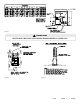
HEAT EXCHANGER
The heat exchanger is connected to the engine cooling line or radiator line by connecting an adapter or simply by just
connecting with a rubber hose. Assure that you have sufficient flow as to the manufacturer’s recommendations of the
engine, and that you are on the hot or outlet side of the engine. The hot water heat exchanger will handle 3 GPM,
maximum. If engine requires more than 3 GPM, a bypass must be used.
(See Fig. 3)
Two 1/2” N.P.T. female brass
fittings are on the tank to hook up to the heat exchanger for connection to engine coolant. Because of the diversity of
marine cooling configurations, it is not possible to provide universal installation instructions; the installer MUST follow
engine manufacturer’s recommendations. FIGURE 3 IS INTENDED ONLY AS A GENERAL GUIDELINE TO SHOW
HOW A PORTION OF THE ENGINE COOLANT MAY BE DIVERTED TO THE OPTIONAL HEAT EXCHANGER.
NOTE: Some marine engines run at higher temperatures than the range of the pressure relief valve on the water
heater. For use with these engines, an alternate location for source water will have to be selected.
LP-03 PAGE: 2 5/17/05
CAUTION
You must always vent air from the water heater when ever a new water supply hook-up is
made. WARNING: TANK MUST BE FULL OF WATER BEFORE POWER IS TURNED ON!
Heating element will be damaged if energized for even a short time while tank is dry.