OPERATING AND MAINTENANCE MANUAL FOR COMMERCIAL ELECTRIC WATER HEATER ELECTRIC HEATER COMPANY BASE MODEL “ E ”
HUBBELL ELECTRIC HEATER COMPANY P.O. BOX 288 STRATFORD, CT 06615 PHONE: (203) 378-2659 FAX: (203) 378-3593 INTERNET: http://www.hubbellheaters.com/ -- IMPORTANT -Always reference the full model number and serial number when calling the factory. WARNING / CAUTION 1. Tank is to be completely filled with water and all air is to be vented before energizing. 2. Due to the rigors of transportation, all connections should be checked for tightness before heater is placed in operation. 3.
TABLE OF CONTENTS SECTION TITLE PAGE # I GENERAL DESCRIPTION AND CONSTRUCTION 5 II INSTALLATION 8 III SCHEDULED MAINTENANCE AND OPERATION 10 IV TROUBLESHOOTING 12 V SERVICING & REPLACEMENT OF PARTS 13 VI MISCELLANEOUS CHARTS AND FORMULAS 21 3
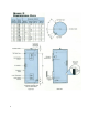
SECTION I - GENERAL DESCRIPTION AND CONSTRUCTION GENERAL DESCRIPTION This book describes a packaged electric water heater that is a stationary, self-contained unit. The complete assembly consists of the storage tank, immersion electric heating element(s), thermostat(s), safety relief valve, safety high temperature cut out, and any other required electrical operating control. Optional equipment may be supplied with your unit. Please consult the product drawing for details specific to your assembly.
CONTROL THERMOSTAT The water heater is supplied as standard with a surface mounted thermostatic switch that is installed and wired at the factory. As an option an immersion thermostat is available. See drawing for specific details. The surface mounted thermostat can be adjusted through a range of 110° - 170° F. The immersion thermostat can be adjusted through a range of 100° - 190° F. Both thermostats are adjustable with a flat tip screwdriver.
OUTER SHELL AND INSULATION The tank is encapsulated in 2-inch thick polyurethane foam insulation. The insulation is protected by a high impact non-corroding colorized composite protective jacket. OPTIONS The following optional features may be included in your water heater. Reference included drawing specific to your heater for further details.
SECTION II – INSTALLATION WARNING / CAUTION DO NOT TURN ON THE ELECTRIC POWER SUPPLY to this equipment until heater is completely filled with water and all air has been released. If the heater is NOT filled with water when the power is turned on, the heating elements will burn out.
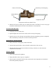
Outlet to floor drain Install into provided tapping Manual Release Lever Temperature Probe Temperature and Pressure Relief Valve 4. Install a relief valve overflow pipe to a nearby floor drain. CAUTION: No valve of any type should be installed between the relief valve and tank or in the drain line. FILLING THE HEATER 1. Completely close the drain valve. 2. Open the highest hot water faucet to allow all air to escape from piping. 3.
SECTION III - SCHEDULED MAINTENANCE AND OPERATION WARNING / CAUTION Before performing any maintenance procedure, make certain power supply is OFF and cannot accidentally be turned on. MAINTENANCE AND OPERATION The water heater is automatic in its operation. It will maintain a full tank of water at the temperature setting of the thermostat. The water heater should not be turned on without first making sure that the tank is full of water and that all air has been released.
ANNUAL INSPECTION 1. Flush tank as follows a. b. c. d. Shut off power supply. Close valve on hot water outlet piping. Open valve on drain piping. Cold water inlet line pressure will be strong enough to flush sediment from the bottom of the tank out through the drain. Let water run for 3-4 minutes. e. Close drain valve. f. Open hot water valve. g. Turn power supply ON.
SECTION IV – TROUBLESHOOTING Symptom No hot water Probable Cause Circuit breaker tripped at source. High limit switch tripped. Loose wires. Heating element inoperable. Low line voltage. Faulty thermostat. Faulty low water cut-off, if installed. Water temperature below settings at all times Faulty thermostat.
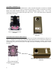
SECTION V - SERVICING & REPLACEMENT OF PARTS WARNING / CAUTION Before servicing or replacing any part make sure to turn the power supply switch to the OFF position. SURFACE TEMPERATURE HIGH LIMIT CUT-OFF 1. Disconnect power from unit. 2. Remove access cover. 3. Disconnect the four (4) 14 gauge wires or three (3) 14 gauge wires and a jumper, as required. Control Wires Manual Reset High-Limit Cut-Off Switch Control Wires Temperature Controller 4.
IMMERSION TEMPERATURE HIGH LIMIT CUT-OFF 1. Disconnect power from unit. 2. Remove access cover. 3. Remove high limit cover screw and cover. Cover Cover Screw Reset Switch 4. Disconnect the two (2) 14 gauge wires. Wires Capillary Tube 5. Remove capillary tube and bulb from thermowell 6. Remove two (2) mounting screws. Mounting Screws 7. Remove control and install new high limit switch by performing above steps in reverse order.
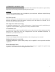
HEATING ELEMENT 1. Disconnect power from unit. 2. Shut off incoming water supply. 3. Attach hose to drain connection. 4. Lift manual release lever on relief valve to let air into system or break union on outgoing water line. 5. Drain water from tank. 6. Disconnect the wires from the heating element terminals. Tank Flange Wires 7. Remove the 3/8-16 nuts. 8. Withdraw element assembly and remove gasket. Gasket Element Assembly Nuts 9. Install new gasket and insert new heating element. 10.
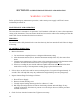
L1 L1 L2 L3 L2 1 3 2 1 3 2 4 1 4 2 1 2 1 3 2 Single Element Operation 1 4 2 3 Ø Open Delta Wiring for Simultaneous Operation 16
L1 1 2 L2 L1 3 4 1 1 2 L2 3 4 1 4 4 2 2 1 1 2 2 Interlocked for Non-Simultaneous Operation Non-Interlocked for Simultaneous Operation 17
SURFACE MOUNTED THERMOSTAT 1. Disconnect power from unit. 2. Remove access cover and locate thermostat. 3. Disconnect the two (2) or three (3) 14 gauge wires and jumpers, as required. Control Wires 4. Remove two (2) mounting screws and disconnect from high limit cut-off, if required. Mounting Screws 5. Replace thermostat using the reverse procedure.
IMMERSION THERMOSTAT 1. Disconnect power from unit. 2. Remove access cover and locate thermostat. 3. Remove high limit cover screw and cover. Cover Cover Screw 4. Disconnect the two (2) or three (3) 14 gauge wires, as required. Wires Capillary Tube 5. Remove capillary tube and bulb from thermowell. 6. Remove two (2) mounting screws. Mounting Screws 7. Replace thermostat using reverse procedure. (Note: Be sure to place capillary tube into slot in base prior to installing cover.
RELIEF VALVE 1. Disconnect power from unit. 2. Shut off incoming water supply. 3. Lift test lever on relief valve to relieve pressure in tank. 4. Disconnect overflow piping. 5. Unscrew relief valve, remove assembly and replace with new one. 6. Connect overflow piping. 7. Turn on incoming water supply and check for leaks. 8. Turn safety switch to ON position.
SECTION VI – MISCELLANEOUS CHARTS AND FORMULAS ELEMENT CHART Element Part # CH-FO-358 CH-FO-408 CH-FO-508 CH-FO-608 CH-FO-304 CH-FO-354 CH-FO-404 CH-FO-454 CH-FO-504 CH-FO-604 TGB-1203-480 TGB-1353-480 TGB-2257L TGB-1207-240 TGB-1303-480 TGB-1403-480 TGB-2257-240 TGB-2257-480 TGB-2457-277 TGB-2457-480 TGB-2503-480 TGB-2507-277 TGB-2603-277 TGB-2603-480 120V ---------2000 ---------------1500 ------2500 500 ------------------------------- Power (Watts) 208V 240V 277V 3500 ------4000 ------5000 ------6000 -
FORMULAS 22
TORQUE VALUES BOLT SIZE 18-8 S/S IN.-LBS. BRASS IN.-LBS. 4-40 4-48 5-40 5-44 6-32 6-40 8-32 8-36 10-24 10-32 1/4-20 1/4-28 5/16-18 5/16-24 3/8-16 3/8-24 7/16-14 7/16-20 1/2-13 1/2-20 9/16-12 9/16-18 5/8-11 5/8-18 3/4-10 3/4-16 7/8-9 7/8-14 1-8 1-14 5.2 6.6 7.7 9.4 9.6 12.1 19.8 22.0 22.8 31.7 75.2 94.0 132 142 236 259 376 400 517 541 682 752 1110 1244 1530 1490 2328 2318 3440 3110 4.3 5.4 6.3 7.7 7.9 9.9 16.2 18.0 18.6 25.9 61.5 77.