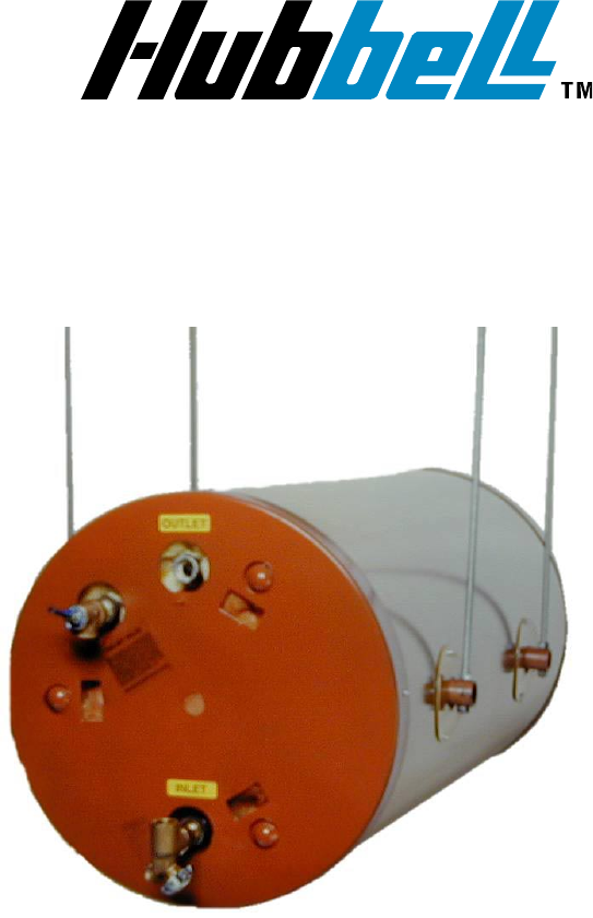
OPERATING AND MAINTENANCE MANUAL FOR COMMERCIAL HORIZONTAL CEILING-HUNG ELECTRIC WATER HEATER ELECTRIC HEATER COMPANY BASE MODELS “ HE and HSE ”
HUBBELL ELECTRIC HEATER COMPANY P.O. BOX 288 STRATFORD, CT 06615 PHONE: (203) 378-2659 FAX: (203) 378-3593 INTERNET: http://www.hubbellheaters.com/ -- IMPORTANT -Always reference the full model number and serial number when calling the factory. WARNING / CAUTION 1. Tank is to be completely filled with water and all air is to be vented before energizing. 2. Due to the rigors of transportation, all connections should be checked for tightness before heater is placed in operation. 3.
TABLE OF CONTENTS SECTION TITLE PAGE # I GENERAL DESCRIPTION AND CONSTRUCTION 5 II INSTALLATION 8 III SCHEDULED MAINTENANCE AND OPERATION 11 IV TROUBLESHOOTING 13 V SERVICING AND REPLACEMENT OF PARTS 14 VI MISCELLANEOUS CHARTS AND FORMULAS 20 3
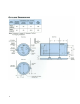
SECTION I - GENERAL DESCRIPTION AND CONSTRUCTION GENERAL DESCRIPTION This book describes a packaged electric water heater that is a stationary, self-contained unit. The complete assembly consists of the storage tank, immersion electric heating element(s), thermostat, safety relief valve, safety high temperature cut out, and any other required electrical operating control. Optional equipment may be supplied with your unit. Please consult the product drawing for details specific to your assembly.
TEMPERATURE HIGH LIMIT SWITCH As a safety device, a surface mounted high temperature cut-off switch with manual reset, factory set at 190° F is provided. In the event of an over-temperature condition, the thermostat will disengage the power from the unit, (in the HSE model the thermostat will disengage the operating coils in the magnetic contactor). The high limit must be manually reset thereafter to restart the heater.
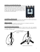
MAGNETIC CONTACTOR (HSE Models Only) The magnetic contactor(s) is a heavy-duty resistive load type rated for 100,000 cycles. The contactor supplies power to the heating element(s) based on the resistive load (non-inductive) of the heater only when the thermostatic switch is engaged, thereby pulling in the contacts until the desired temperature is reached. At this point, the contacts will drop out, which in turn disconnects power from the elements.
SECTION II – INSTALLATION WARNING / CAUTION DO NOT TURN ON THE ELECTRIC POWER SUPPLY to this equipment until heater is completely filled with water and all air has been released. If the heater is NOT filled with water when the power is turned on, the heating elements will burn out.
PIPING INSTALLATION NOTE: The most effective means for preventing deterioration from accelerated corrosion due to galvanic and stray current is the installation of dielectric fittings/unions. The installation of these fittings is the responsibility of the installing contractor. 1. Thread cold water inlet and diffuser assembly into tank. Diffuser slots must be pointing down toward the bottom of the tank. Cold Water Inlet Diffuser Diffuser Slots Drain Valve 2.
FILLING THE HEATER 1. Completely close the drain valve. 2. Open the highest hot water faucet to allow all air to escape from piping. 3. Open the valve to the cold water inlet and allow the heater and piping system to completely fill, as indicated by a steady flow of water from the open faucet. ELECTRICAL INSTALLATION 1. Enter electric enclosure with properly sized feeder leads. Single-phase installations require two (2) leads; three phase installations require three (3) leads. 2.
SECTION III - SCHEDULED MAINTENANCE AND OPERATION WARNING / CAUTION Before performing any maintenance procedure, make certain power supply is OFF and cannot accidentally be turned on. MAINTENANCE AND OPERATION The water heater is automatic in its operation. It will maintain a full tank of water at the temperature setting of the thermostat. The water heater should not be turned on without first making sure that the tank is full of water and that all air has been released.
4. Inspect ceiling supports for tightness and/or damage. 5. Check for loose electrical connections. Tighten as necessary. ANNUAL INSPECTION 1. Flush tank as follows a. b. c. d. Shut off power supply. Close valve on hot water outlet piping. Open valve on drain piping. Cold water inlet line pressure will be strong enough to flush sediment from the bottom of the tank out through the drain. Let water run for 3-4 minutes. e. Close drain valve. f. Open hot water valve. g. Turn power supply ON.
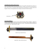
SECTION IV – TROUBLESHOOTING Symptom No hot water Probable Cause Circuit breaker tripped at source. High limit switch tripped. Corrective Action / Remedy Reset circuit breaker. Reset high limit switch. Loose wires. Tighten wires. Torque screws per torque chart included in Section VI. Check heating element operation by clamping an Amprobe around each wire to the element. The ampere reading should agree with the nameplate ‘AMP’ figure. Have source electrical system checked by an electrician.
SECTION V - SERVICING & REPLACEMENT OF PARTS WARNING / CAUTION Before servicing or replacing any part make sure to turn the power supply switch to the OFF position. SURFACE TEMPERATURE HIGH LIMIT CUT-OFF 1. Disconnect power from unit. 2. Remove access cover. 3. Disconnect the four (4) 14 gauge wires. Control Wires 4. Remove the two (2) mounting screws. Mounting Screws 5. Replace control and install new high limit switch by performing above steps in reverse order.
HEATING ELEMENT 1. Disconnect power from unit. 2. Shut off incoming water supply. 3. Attach hose to drain connection. 4. Lift manual release lever on relief valve to let air into system or break union on outgoing water line. 5. Drain water from tank. 6. Disconnect the wires from the heating element terminals. 7. Remove the 3/8-16 nuts. Tank Flange Element Terminals Nuts 8. Withdraw element assembly and remove gasket. Gasket Element Assembly 9. Install new gasket and insert new heating element. 10.
IMMERSION THERMOSTAT 1. Disconnect power from unit. 2. Remove access cover and locate thermostat. 3. Remove high limit cover screw and cover. Cover Cover Screw 4. Disconnect the two (2) 14 gauge wires. Wires Capillary Tube 5. Remove capillary tube and bulb from thermowell. 6. Remove two (2) mounting screws. Mounting Screws 7. Replace thermostat using reverse procedure. (Note: Be sure to place capillary tube into slot in base prior to installing cover.
MAGNETIC CONTACTOR 1. Disconnect power from unit. 2. Disconnect line and load wires to contactor. 3. Disconnect two (2) 14 gauge control circuit wires. Control Wires Line Wires Load Wires 4. Loosen two (2) holding screws and remove contactor. Mounting Screws (Bottom screw not shown) 5. Replace with new contactor using reverse procedure.
RELIEF VALVE 1. Disconnect power from unit. 2. Shut off incoming water supply. 3. Lift test lever on relief valve to relieve pressure in tank. 4. Disconnect overflow piping. 5. Unscrew relief valve, remove assembly and replace with new one. 6. Connect overflow piping. 7. Turn on incoming water supply and check for leaks. 8. Turn safety switch to ON position.
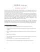
SECTION VI – MISCELLANEOUS CHARTS AND FORMULAS FORMULAS 3-PHASE ELEMENT CHART Power (kW) Element Part # 208V 240V 480V 2-38683N 3 4 2.5 3-38683N 3 4 5 4-38683N 4 5 6 5-38683N 5 6 8 6-38683N 6 8 10 7-38683N 8 10 12 8-38683N 12 15 10 9-38683N 12 15 20 10-38683N 15 20 ---11-38683N 17.3 ---- ---- 20 Immersion Length 13" 13" 13" 13" 13" 13" 13" 15" 15" 15" Hairpin 57.6 43.2 34.4 27.9 21.6 17.1 14.4 12.1 9.1 7.5 Resistance (Ohms) 1Φ 3 Φ DELTA 19.2 57.6 14.4 43.2 11.5 34.4 9.3 27.9 7.2 21.6 5.7 17.1 4.8 14.
SINGLE PHASE ELEMENT CHART Element Part # CH-FO-358 CH-FO-408 CH-FO-508 CH-FO-608 CH-FO-304 CH-FO-354 CH-FO-404 CH-FO-454 CH-FO-504 CH-FO-604 TGB-1203-480 TGB-1353-480 TGB-2257L TGB-1207-240 TGB-1303-480 TGB-1403-480 TGB-2257-240 TGB-2257-480 TGB-2457-277 TGB-2457-480 TGB-2503-480 TGB-2507-277 TGB-2603-277 TGB-2603-480 120V ---------2000 ---------------1500 ------2500 500 ------------------------------- Power (Watts) 208V 240V 277V 3500 ------4000 ------5000 ------6000 ---------3000 4000 2500 3500 ---300
TORQUE VALUES BOLT SIZE 18-8 S/S IN.-LBS. BRASS IN.-LBS. 4-40 4-48 5-40 5-44 6-32 6-40 8-32 8-36 10-24 10-32 1/4-20 1/4-28 5/16-18 5/16-24 3/8-16 3/8-24 7/16-14 7/16-20 1/2-13 1/2-20 9/16-12 9/16-18 5/8-11 5/8-18 3/4-10 3/4-16 7/8-9 7/8-14 1-8 1-14 5.2 6.6 7.7 9.4 9.6 12.1 19.8 22.0 22.8 31.7 75.2 94.0 132 142 236 259 376 400 517 541 682 752 1110 1244 1530 1490 2328 2318 3440 3110 4.3 5.4 6.3 7.7 7.9 9.9 16.2 18.0 18.6 25.9 61.5 77.