
User's Manual


Pub. 42004-693L2C
Model 69320-101 Voice Network Adapter Page: 4 of 15
\\s_eng\gtcproddocs\standard ioms - current release\42004 instr. manuals\42004-693l2c.doc
04/06
Switch and Jumper Settings
Overview
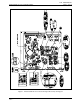
Several switch and jumper settings are required for proper operation of the VNA Card. The following
settings are set during the system commissioning and programming and should not be changed. If replacing
an existing 69266-001 T1 card or VNA card for maintenance purposes, be sure to replicate the switch and
jumper setting of the card being replaced. Refer to Figure 1 for the switch and jumper locations.
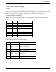
Front Panel DIP Switch (SW5) Settings
NOTE: The front panel DIP switches (SW5) can be updated without powering down the card rack and
without resetting the MCU.
Position Number Name
Top 1 Line Build 0 (LB0)
2 Line Build 1 (LB1)
3 Line Build 2 (LB2)
4 Receive Equalizer Gain Limit
5 Lamp Test
6 Customer Disconnect Enable
7 Local Loop Back
Bottom 8 Remote Loop Back
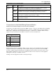
The Line Build # switches control the “line build” (signal’s amplitude) of the T1 transmit line. Set the Line
Build # switches according to the following table:
LB0 LB1 LB2 T1 Line Length
Open Open Open DSX-1 (0 to 133 feet) / 0 dB CSU
Open Open Closed DSX-1 (133 to 266 feet)
Open Closed Open DSX-1 (266 to 399 feet)
Open Closed Closed DSX-1 (399 to 533 feet)
Closed Open Open DSX-1 (533 to 655+ feet)
Closed Open Closed -7.5 dB CSU
Closed Closed Open -15 dB CSU
Closed Closed Closed -22.5 dB CSU