
User's Manual


Pub. 42004-693L2C
Model 69320-101 Voice Network Adapter Page: 5 of 15
\\s_eng\gtcproddocs\standard ioms - current release\42004 instr. manuals\42004-693l2c.doc
04/06
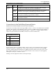
The Receive Equalizer Gain Limit switch controls the similarly named feature of the T1 transceiver. Set
the Receive Equalizer Gain Limit switch according to the following table:
Open
-36 dB (long haul)
Closed
-15 dB (limited long haul)
The Lamp Test switch turns on all LEDs on the VNA’s front panel. It is used during production of the
VNA. The Lamp Test switch will not function when the VNA detects the MCU (MCU FLT LED is Off).
Set the Lamp Test switch according to the following table:
Open
All front panel LEDs function normally.
Close
All front panel LEDs are ON
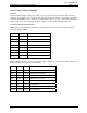
The Customer Disconnect function presents a well-behaved signal on the T1 line. This signal is sometimes
useful during troubleshooting and verification. Set the Customer Disconnect Enable switch according to the
following table:
Open
The T1 transceiver is operating normally.
Closed
The Customer Disconnect signal is being transmitted on the T1 line. This setting disrupts the
T1 signal and the MCU reports a T1 line fault.
The Local Loop Back feature sometimes is used during troubleshooting. Set the Local Loop Back switch
according to the following table:
Open
The T1 transceiver is operating normally.
Closed
The “Framer Loopback” feature of the T1 transceiver is enabled. The T1 transceiver transmits
the Blue Alarm on the T1 transmit line during this condition. This setting disrupts the T1 signal
and the MCU reports a T1 line fault. This setting causes the VNA to receive the T1 signal it
normally would transmit, while actually transmitting the Blue Alarm.
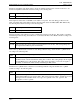
The Remote Loop Back feature sometimes is used during troubleshooting. Set the Remote Loop Back
switch according to the following table:
Open
The T1 transceiver is operating normally.
Closed
The “Remote Loopback” feature of the T1 transceiver is enabled. This setting disrupts the T1
signal and the MCU reports a T1 line fault. This setting causes the VNA to transmit its received
T1 signal. The T1 standards mention two types of loopbacks: “line” and “payload”; this
loopback is a “line” loopback.