323 Operations Manual 531444-1_C
Thank You! Thank you for choosing Humminbird®, America's #1 name in fishfinders. Humminbird® has built its reputation by designing and manufacturing top-quality, thoroughly reliable marine equipment. Your Humminbird® is designed for trouble-free use in even the harshest marine environment. In the unlikely event that your Humminbird® does require repairs, we offer an exclusive Service Policy - free of charge during the first year after purchase, and available at a reasonable rate after the one-year period.
Table of Contents How Sonar Works 1 DualBeam PLUS™ Sonar...................................................................................................................... 4 What’s On the Display 5 Views 7 Sonar View.............................................................................................................................................. 8 Understanding Sonar History............................................................................................................
Table of Contents Bottom View........................................................................................................................................ 28 Zoom Level (Sonar Zoom view only) ................................................................................................ 29 Bottom Lock (Sonar Zoom view only) .............................................................................................. 29 Bottom Range (Sonar Zoom View only, when Bottom Lock is On) ................
Table of Contents Depth Offset (Advanced) .................................................................................................................. 50 Temp Offset (Advanced) .................................................................................................................... 50 Speed Calibration (Advanced, with Temp/Speed only) ................................................................ 51 Troubleshooting 52 300 Series™ Doesn’t Power Up .......................................
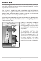
How Sonar Works Sonar technology is based on sound waves. The 300 Series™ Fishing System uses sonar to locate and define structure, bottom contour and composition, as well as depth directly below the transducer. Your 300 Series™ Fishing System sends a sound wave signal and determines distance by measuring the time between the transmission of the sound wave and when the sound wave is reflected off of an object; it then uses the reflected signal to interpret location, size, and composition of an object.
When all the echoes are viewed side by side, an easy to interpret "graph" of the bottom, fish and structure appears. The sound pulses are transmitted at various frequencies depending on the application. Very high frequencies (455 kHz) are used for greatest definition but the operating depth is limited. High frequencies (200 kHz) are commonly used on consumer sonar and provide a good balance between depth performance and resolution.
The power output is the amount of energy generated by the sonar transmitter. It is commonly measured using two methods: • Root Mean Square (RMS) measures power output over the entire transmit cycle. • Peak to Peak measures power output at the highest points. The benefits of increased power output are the ability to detect smaller targets at greater distances, ability to overcome noise, better high speed performance and enhanced depth capability.
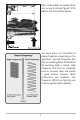
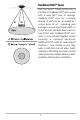
DualBeam PLUS™ Sonar Your 300 Series™ Fishing System uses a 200/83 kHz DualBeam PLUS™ sonar system with a wide (60°) area of coverage. DualBeam PLUS™ sonar has a narrowly focused 20° center beam, surrounded by a second beam of 60°, expanding your coverage to an area equal to your depth. In 20 feet of water, the wider beam covers an area 20 feet wide. DualBeam PLUS™ sonar returns can be blended together, viewed separately or compared side-by-side.
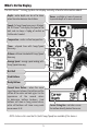
What’s On the Display The 300 Series™ Fishing System can display a variety of useful information about Depth - water depth; can be set to alarm when the water becomes too shallow. Cursor - available in Freeze Frame and to provide depth of a sonar return and Speed - if a Temp/Speed accessory is attached, the 300 Series™ can display the speed of the boat, and can keep a Triplog of nautical or statute miles traveled. Temperature - water surface temperature. Timer - elapsed time with Temp/Speed Accessory.
the area under and adjacent to your boat, including the following items: 83 kHz, Wide Beam Hollow Fish Symbol can be positioned in the Sonar View bottom depth below the cursor. Structure - where fish may be hiding. Fish - fish are displayed as arches and/or fish icons, and the unit can be set to alarm when a fish of a certain size is detected. When a target is detected and Fish ID+ is on, a Fish ID+TM symbol with depth is displayed. The size of the symbol shows the intensity of the sonar return.
Views The views available on your 300 Series™ Fishing System are: • • • • • Sonar View Zoom View 200/83 kHz Split Sonar View Big Digits View Circular Flasher View. Sonar View is the default view. When the VIEW key is pressed, the display cycles through the available views. When the EXIT key is pressed, the display cycles through the available views in reverse order. Any view can be hidden or displayed as part of the view rotation using the Views Menu tab.
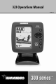
Sonar View Sonar View presents a historical log of sonar returns. Depth is always displayed. Readouts for temperature and speed are automatically displayed if the appropriate accessory is connected. The most recent sonar returns are charted on the right side of the window; as new information is received, the older information is moved across the display to the left. A Digital Depth Readout is displayed in the upper left corner.
Understanding Sonar History It is important to understand the significance of the 300 Series™ Fishing System display. The display does NOT show a literal 3-dimensional representation of what is under the water. Each vertical band of data received by the control head and plotted on the display represents something that was detected by a sonar return at a particular time.
Real Time Sonar (RTS®) Window A Real Time Sonar (RTS®) Window appears on the right side of the display in the Sonar View only. The RTS® Window always updates at the fastest rate possible for depth conditions and shows only the returns from the bottom, structure and fish that are within the transducer beam. The RTS® Window plots the depth and intensity of a sonar return (see Sonar Menu - RTS® Window). The Wide RTS® Window indicates the sonar intensity through the use of a bar graph.
Bottom Presentation As the boat moves, the unit charts the changes in depth on the display to create a profile of the Bottom Contour. The type of bottom can be determined from the return charted on the display. A Hard Bottom such as compacted sediment or flat rock appears as a thinner line across the display. A Soft Bottom such as mud or sand appears as a thicker line across the display. Rocky Bottoms have a broken, random appearance. Bottom Contour Profile with RTS® Window.
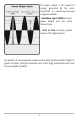
Inverse is a method where weak returns are shown with dark pixels and strong returns with lighter pixels. This has the benefit of ensuring that weak signals will be clearly visible on the display. Structure ID® represents weak returns as light pixels and strong returns as dark pixels. This has the benefit of ensuring that strong returns will be clearly visible on the display. WhiteLine® highlights the strongest sonar returns in white, resulting in a distinctive outline.
Sonar Zoom View Sonar Zoom View increases the displayed resolution to separate sonar returns that are very close together, such as those caused by fish suspended close to the bottom or within structure. In Zoom View, the display is split to show a narrow slice of the full range view on the right and the zoomed view on the left.
200/83 kHz Split Sonar View Split Sonar View displays sonar returns from the 83 kHz wide beam on the left side of the screen and displays sonar returns from the 200 kHz narrow beam on the right side of the screen. Depth is always displayed in the upper left hand corner. You can use the Split Sonar View to make side by side comparisons between the sonar returns from the 83 kHz wide beam and the 200 kHz narrow beam.
Big Digits View Big Digits View provides digital data in a large, easy-to-see format. Depth is always displayed. Readouts for temperature, speed and Triplog information are displayed automatically if the appropriate accessory is connected to the system. The Triplog shows distance traveled, average speed, and time elapsed since the Triplog was last reset. The digital readouts in the Big Digits View cannot be customized.
Key Functions Your 300 Series™ Fishing System user interface consists of a set of easy-to-use keys that work with various on-screen views and menus to give you flexibility and control over your fishing experience. POWER/LIGHT Key The POWER/LIGHT key is used to turn the 300 Series™ Fishing System on and off, and also to adjust the backlight and contrast of the display. Press the POWER/LIGHT key to turn the unit on. The Title screen is then displayed until the Fishing System begins sonar operation.
MENU Key The MENU key is used to access the menu system. Start-Up Options Menu - Press the MENU key during the power up sequence to view the Start-Up Options menu. X-PressTM Menu - Press the MENU key once for the Sonar X-PressTM Menu. The X-PressTM Menu allows you to access frequently-used settings without having to navigate through the whole menu system. When the X-PressTM Menu is displayed, you can use the UP or DOWN Cursor keys to move to a particular menu choice.
EXIT Key The EXIT key has multiple functions, depending on the situation: • If an alarm is sounding, pressing EXIT will cancel the alarm. • If a menu tab is selected, pressing EXIT will exit the menu mode and return to the view. • If a menu is active, pressing EXIT will return to the previous level in the menu system. • Pressing EXIT will cycle through the available views in reverse order. • If Freeze Frame is active, pressing EXIT will return to a scrolling display.
The Menu System The menu system is divided into easy-to-use menu modules. The main components of the menu system are: Start-Up Options Menu - Press the MENU key during the power up sequence to view the Start-Up Options menu. X-PressTM Menu - The X-PressTM Menu allows you to access the settings that are changed frequently without having to navigate through the whole menu system. Press the MENU key once to display the X-PressTM Menu.
User Mode (Normal or Advanced) - An Advanced Mode is provided for users who desire the highest level of control over the Fishing System and Normal Mode for users who desire greater simplicity and fewer menu choices. Additional Advanced menu choices will be displayed throughout the menu system when you navigate to specific menus while in Advanced Mode. Any changes made while in Advanced Mode will remain in effect after you switch back to Normal Mode.
Start-Up Options Menu Press the MENU key when the Title screen is displayed to access the Start-Up Options menu. Use the UP or DOWN 4-WAY Cursor keys to position the cursor, then the RIGHT Cursor key to select one of the following choices. If you wait too long, the system will default to whichever menu mode happens to be highlighted: • Normal • Simulator • System Status. Start-Up Options Menu See the following paragraphs for more information about each of these choices.
Simulator Use the Simulator to learn how to use your 300 Series™ Fishing System before taking your boat on the water. The Simulator is a very powerful tool that simulates on the water operation, providing a randomly-updated display. We recommend going through this manual while using the Simulator, since all of the menus function and affect the display the way they actually do when in Normal operation.
System Status Use System Status to view system connections and to conduct a unit self-test. The following screens are displayed in turn when you press the VIEW button when using System Status: System Status Self Test Screen • Self Test • Accessory Test. Self Test displays results from the internal diagnostic self test, including unit serial number, Printed Circuit Board (PCB) serial number, software revision, total hours of operation and the input voltage.
Sonar X-PressTM Menu The Sonar X-PressTM Menu provides access to the settings most frequently-used. Press the MENU key once while in any of the Sonar Views to access the Sonar XPressTM Menu. NOTE: Upper Range only appears in Advanced User Mode when in Sonar, Split Sonar, Big Digits and Circular Flasher Views. NOTE: Zoom Level only appears in Sonar Zoom View.
Sensitivity Sensitivity controls how much detail is shown on the display and will adjust the sensitivity of all sonar frequencies. Increasing the sensitivity shows more sonar returns from small baitfish and suspended debris in the water; however, the display may become too cluttered. When operating in very clear water or greater depths, increased sensitivity shows weaker returns that may be of interest.
Upper Range (Advanced: Sonar, Split Sonar, Big Digits and Circular Flasher Views only) Upper Range sets the shallowest depth range that will be displayed on the Sonar, Split Sonar, Big Digits and Circular Flasher views. The Upper Range menu choice is available when User Mode is set to Advanced (see Setup Menu Tab: User Mode) and can only be accessed from the Sonar, Split Sonar, Big Digits and Circular Flasher views. Upper Range is often used with Lower Range.
Lower Range Lower Range sets the deepest depth range that will be displayed. Automatic is the default setting. When in automatic mode, the lower range will be adjusted by the unit to follow the bottom. Selecting a specific setting locks the depth range into Manual mode. Use both Upper and Lower Range together to view a specific depth range manually when looking for fish or bottom structure.
Chart Speed Chart Speed determines the speed at which the sonar information moves across the display, and consequently the amount of detail shown. A faster speed shows more information and is preferred by most anglers; however, the sonar information moves across the display quickly. A slower speed keeps the information on the display longer, but the bottom and fish details become compressed and may be difficult to interpret.
To adjust the Bottom View: 1. Highlight Bottom View on the Sonar X-PressTM Menu. 2. Use the LEFT or RIGHT 4-WAY Cursor Control keys to change the Bottom View setting. (Inverse, Structure ID®, WhiteLine®, Bottom Black, Default = Inverse) Zoom Level (Sonar Zoom View only) Zoom Level sets the magnification level for the Sonar Zoom View, and is only available on the X-PressTM Menu when the Sonar Zoom View is active.
Bottom Range (Sonar Zoom View only, when Bottom Lock is On) Bottom Range allows you to control how much of the water column, measured up from the bottom, is shown in the Sonar Zoom View. Choose a small value to see lowlying bottom structure or details of the bottom return. Choose a larger value to see large structure in deeper water. It is possible to set the Bottom Range to be greater than the depth. In this case, you may see surface clutter in a wavy band that mirrors changes in the depth.
Sonar Menu Tab Press the MENU key twice to access the Main Menu System and then press the RIGHT Cursor key to select the Sonar tab. NOTE: Menu choices will vary depending on system settings such as whether the unit is set for Advanced User mode or what transducer is currently selected.
Beam Select Beam Select sets which sonar returns from the transducer will be displayed on the screen. When set to 200/83 kHz, the returns from both beams are blended by starting with the 83 kHz wide beam return, dimming it, and then overlaying it with the 200 kHz narrow beam return. The darker 200 kHz narrow beam sonar returns will stand out from the paler 83 kHz wide beam sonar returns. The Split Sonar View continues to display the sonar returns from each beam in their respective windows.
Fish ID+TM Fish ID+TM uses advanced signal processing to interpret sonar returns, and will display a Fish Symbol when very selective requirements are met. When a fish is detected, a fish icon and its depth are displayed above the return that has been classified as being a fish. Three different fish size icons represent the intensity of the sonar return, and provide an indicator of relative fish size.
Fish ID Sensitivity Fish ID Sensitivity adjusts the threshold of the Fish ID+TM detection algorithms. Selecting a higher setting allows weaker returns to be displayed as fish. This is useful for identifying smaller fish species or baitfish. Selecting a lower setting displays fewer fish from weak sonar returns. This is helpful when seeking larger species of fish. Fish ID Sensitivity is used in conjunction with Fish ID+TM.
Zoom Width Zoom Width adjusts the width of the Zoom window on the Sonar Zoom View. To change the Zoom Width Setting: 1. Highlight Zoom Width on the Sonar main menu. 2. Use the LEFT or RIGHT 4-WAY Cursor Control keys to change the Zoom Width setting. (Narrow, Medium, Wide, Default = Wide) 83 kHz Sensitivity (Advanced) 83 kHz Sensitivity changes the sensitivity of the 83 kHz beam.
Depth Lines (Advanced) Depth Lines divide the display into four equal sections which are separated by three horizontal depth lines. The depth of each line is displayed along the depth scale. You can either turn Depth Lines On or Off. The Depth Lines menu choice is available when User Mode is set to Advanced (see Setup Menu Tab: User Mode). Depth Lines Depth Lines To change the Depth Lines setting: 1. Make sure you are in Advanced User Mode, then highlight Depth Lines on the Sonar main menu. 2.
Surface Clutter (Advanced) Surface Clutter adjusts the filter that removes surface clutter noise caused by algae and aeration. The lower the setting, the less surface clutter will be displayed. The Surface Clutter menu choice is available when User Mode is set to Advanced (see Setup Menu Tab: User Mode). Surface Clutter To change the Surface Clutter setting: 1. Make sure you are in Advanced User Mode, then highlight Surface Clutter on the Sonar main menu. 2.
Noise Filter (Advanced) Noise Filter adjusts the sonar Noise Filter to limit interference on the display from sources such as your boat engine, turbulence, or other sonar devices. The Noise Filter menu choice is available when User Mode is set to Advanced (see Setup Menu Tab: User Mode). NOTE: The Off setting removes all filtering; Low, Medium and High settings add progressive filtering of the sonar returns.
Water Type (Advanced) Water Type configures your unit for operation in fresh or salt water. The Water Type menu choice is available when User Mode is set to Advanced (see Setup Menu Tab: User Mode). NOTE: In salt water, what would be considered a large fish might be 2 to 10 times bigger than a large fish in fresh water (depending on the type of fish you are seeking). The salt water setting allows for a greater range in fish size adjustment to account for this.
Alarms Menu Tab From any view, press the MENU key twice to access the Main Menu System. The Alarms tab will be the default selection. NOTE: When an alarm is triggered, you can silence it by pressing any key. The alarm will be silenced, and will not be triggered again until a new instance of the alarm condition is detected.
Depth Alarm Depth Alarm sounds when the depth becomes equal to or less than the menu setting. To change the Depth Alarm setting: 1. Highlight Depth Alarm on the Alarms main menu. 2. Use the LEFT or RIGHT 4-WAY Cursor Control keys to change the Depth Alarm setting. (OFF, 1 to 100 feet, or 0.5 to 30 meters [International Models Only], Default = OFF) Fish ID Alarm Fish ID Alarm sounds when the Fishing System detects fish that correspond to the alarm setting. Fish ID Alarm will only sound if Fish ID+TM is on.
Low Battery Alarm Low Battery Alarm sounds when the input battery voltage is equal to or less than the menu setting. The battery alarm will only sound for the battery that is connected to the 300 Series™ Fishing System. The Low Battery Alarm should be set to warn you when the battery voltage drops below the safety margin that you have determined.
Alarm Tone Alarm Tone selects the pitch of the alarm sound. A brief tone will be produced as you adjust the Alarm Tone so that you can select the tone that you can hear best. To change the Alarm Tone setting: 1. Highlight Alarm Tone on the Alarms main menu. 2. Use the LEFT or RIGHT 4-WAY Cursor Control keys to change the Alarm Tone setting.
Setup Menu Tab From any view, press the MENU key twice to access the tabbed Main Menu System, then press the RIGHT cursor key until the Setup tab is selected. NOTE: Menu choices will vary depending on system settings such as whether the unit is set for Advanced User mode, whether it is an International model, or whether a Temp/Speed is currently connected.
Units - Depth Units - Depth selects the units of measure for all depthrelated readouts. To change the Units - Depth setting: 1. Highlight Units - Depth on the Setup menu. 2. Use the LEFT or RIGHT 4-WAY Cursor Control keys to change the Units - Depth setting. (Meters [International Models Only], Feet, Fathoms; Default is Meters for International models, and Feet for Domestic models) Units - Temp (International only) Units - Temp selects the units of measure for all temperature-related readouts.
Units - Speed (with Temp/Speed) Units - Speed selects the units of measure for speed-related readouts, and will appear in the menu if a Temp/Speed Accessory is connected and the paddlewheel has moved at least once. To change the Units - Speed setting: 1. Highlight Units - Speed on the Setup menu. 2. Use the LEFT or RIGHT 4-WAY Cursor Control keys to change the Units - Speed setting.
Triplog Reset (with Temp/Speed) Triplog Reset resets the Triplog to zero, and will appear in the menu if a Temp/Speed Accessory is connected and the paddlewheel has moved at least once. The Triplog provides the following information: timer for elapsed time, distance traveled since last reset, and average speed. NOTE: See Setup Menu Tab: Select Readouts (Advanced) to find out how to display Triplog information on the screen. To Reset Triplog: 1. Highlight Reset Triplog on the Setup menu. 2.
Select Views (Advanced) Select Views sets the available views to either hidden or visible in the view rotation. The view will be removed from the view rotation if it is set to Hidden and will be displayed in the view rotation if it is set to Visible.
Select Readouts (Advanced, Sonar view only) Select Readouts sets individual digital readouts on the Sonar View. This Advanced feature allows you to select what data will be displayed in each of 5 fixed-position data windows arranged around the left and bottom edges of the Sonar View screen, or whether a particular window will be turned off, displaying nothing in that area; you can access this menu choice only when in Advanced User Mode (see Setup Menu Tab: User Mode.
Depth Offset (Advanced) Depth Offset will adjust the digital depth readout to indicate depth from the waterline or boat's keel. Enter a positive vertical measurement from the transducer to the waterline to read the depth from the waterline. Enter a negative vertical measurement from the transducer to keel to read the depth from the keel. This menu choice is available only when in Advanced User Mode (see Setup Menu Tab: User Mode.) To change the Depth Offset setting: 1.
Speed Calibration (Advanced, with Temp/Speed only) Speed Calibration will adjust the speed readout by the percentage entered, and will appear in the menu if a Temp/Speed Accessory is connected and the paddlewheel has moved at least once, when the unit is in Advanced User Mode (see Setup Menu Tab: User Mode.) To change the Speed Calibration setting: 1. Make sure you are in Advanced User Mode, then highlight Speed Calibration on the Setup menu. 2.
Troubleshooting Before contacting the Humminbird® Customer Resource Center, please read the following section. Taking the time to review these troubleshooting guidelines may allow you to solve a performance problem yourself, and therefore avoid sending your unit back for repair.
Display Problems There are several main conditions or sources of possible interference that may cause problems with the quality of the information displayed on the control head. Look in the following table for some symptoms of display problems and possible solutions: Problem Possible Cause The control head loses power at high speeds. If the power output of your boat’s engine is unregulated, the control head may be protecting itself using its over-voltage protection feature.
Finding the Cause of Noise Electrical noise usually affects the display with many black dots at high speeds, and high sensitivity readings. One or more of the following sources can cause noise or interference: Possible Source of Noise Isolation Other electronic devices Turn off any nearby electronic devices to see if the problem goes away, then turn them on one at a time to see if the noise re-appears.
Specifications Depth Capability ................................................................................ 1000 ft (330 m) Power Output............................................300 Watts (RMS), 2400 Watts (Peak to Peak) Operating Frequency.............................. 200 kHz and 83 kHz DualBeam PLUS™ Area of Coverage .................................................................. 60° @ -10 dB in 83 kHz 20° @ -10 dB in 200 kHz Target Separation ...................................................
Glossary Sonar Terms: Alarm, Depth: Depth Alarm is a user-controllable, audible alert that sounds when depth is less than or equal to the setting. Alarm, Temperature: Temperature Alarm is a user-controllable, audible alert that sounds when the water surface temperature equals the setting. Backlight: Backlight is a user-controllable illumination for the LCD for night and low light use. Beam (Sonar Beam): A sonar beam is the cone-shaped projection of sound waves formed as sound travels underwater.
Chart Speed: Chart Speed is a user-controllable feature that sets the speed at which sonar information moves across the display. A faster setting displays sonar information from more pings and shows more detail, but the information moves quickly across the display; a slower setting permits viewing of more sonar history, but does not display as much detail. The best setting is often the user's personal choice.
Fish Arch: A Fish Arch is the apparent "arch" that appears on the display when any object moves through the sonar cone. The arch results from a gradual decrease in distance to an object as it moves into the sonar cone. The distance to an object changes due to the conical shape of the sonar beam, which causes the distance to be greater at the edges of the beam than at the center of the beam. When this distance change is graphed on the display, an arch appears.
of enhancing the apparent sensitivity because the weaker signals appear bolder. Inverse grayscale works well in very clear water. Debris-laden water often appears as a lot of clutter on the screen. Instant Image Update: Instant Image Update is a Humminbird® feature that updates all the sonar information on the display when Sensitivity and a variety of sonar settings (Bottom View, Range, etc.) are modified.
Pixels: Pixels are the "picture elements", or small square blocks, that make up the image on the LCD. Measured as a vertical by horizontal number (i.e. 640V x 320H), this key specification typically indicates the quality of resolution. In fishfinders, the total resolution (vertical multiplied by horizontal) is often less important than the "Vertical Pixel" resolution. See Pixels, Vertical. Pixels, Vertical: Vertical Pixels are a number of vertical picture elements in a single column on an LCD display.
ability to spot fish and structure over a wide 90° area, and to identify on which side of the boat they are located. See DualBeam PLUS™. Quick Disconnect Mount: The Quick Disconnect Mounting system is an exclusive Humminbird® feature that permits the unit to be easily removed from the mounting base by pressing a release button, and re-installed by simply snapping it back into place. All cable connections are made when installing, so that no separate wiring connections are required.
SONAR: SONAR is the acronym for SOund and NAvigation Ranging. Sonar technology uses precision sound bursts transmitted underwater to determine the distance and other attributes of objects in the water. Distance can be determined because the speed of sound in water is constant, and the time for the signal to return is measured. Sound also travels very quickly underwater, making sonar a responsive, cost-effective tool.
piles) and a wide range of other potential objects (sunken boats, reefs). Humminbird® units excel at showing structure with great detail over a wider area due to unique sonar configurations developed for the angler. Structure ID®: Structure ID® is a Humminbird® feature that describes the traditional grayscale method of presenting sonar information. See Grayscale.
Transducer: The transducer mounts on the boat and is in contact with the water. It converts the electrical energy from the transmitter into sound energy, forming the sonar beam. Internally, the transducer consists of one or more piezo electric disks that expand by very minute amounts to create the sound wave. This element also works in reverse, converting the returned sound energy back into an electrical signal that the receiver interprets.
WhiteLine®: WhiteLine® is a Humminbird® feature that highlights the strongest sonar return on the display using a very light gray band. This is preferred by some anglers who have grown accustomed to the feature on paper graph chart recorders. WideSide®: WideSide® is a Humminbird® sonar configuration used in an optional transducer. WideSide® uses three sonar beams pointing to the left, right and down.
Notes 66
Contact Humminbird® Contact the Humminbird® Customer Resource Center in any of the following ways: By Telephone (Monday - Friday 8:00 a.m. to 4:30 p.m. Central Standard Time): 1-800-633-1468 By e-mail (typically we respond to your e-mail within three business days): cservice@johnsonoutdoors.