
Corp. Refrigerator User Manual


IGSS-ESS/ESSS-0303
8
Electrical
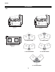
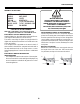
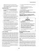
WIRING COLOR CODE
GREEN GROUND
PURPLE ANTI-SWEAT
ORANGE LIGHTS
YELLOW RECEPTACLE
RED / BLACK T-STAT /SOLENOID230V
BLACK / WHITE T-STAT / SOLENOID 115V
BROWN FAN MOTORS
CASE MUST BE GROUNDED
NOTE: Refer to label affixed to case to determine the actual
configuration as checked in the “TYPE INSTALLED” boxes.
ELECTRICAL CIRCUIT IDENTIFICATION
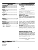
Standard lighting for all models will be full length fluores-
cent lamps located within the case at the top.
The switch controlling the lights, the plug provided for
digital scale, and the thermometer are located at the rear
of the case mullion.
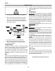
The receptacle that is provided on the exterior back of
these models is intended for computerized scales with a
five amp maximum load, not for large motors or other
high wattage appliances. It should be wired to a dedicated
circuit.
ELECTRICAL SERVICE RECEPTACLES
(When Applicable)
The receptacles located on the exterior of the merchan-
diser are intended for scales and lighted displays. They
are not intended nor suitable for large motors or other
external appliances.
BEFORE SERVICING
ALWAYS DISCONNECT ELECTRICAL
POWER AT THE MAIN DISCONNECT
WHEN SERVICING OR REPLACING ANY
ELECTRICAL COMPONENT.
This includes (but not limited to) Fans, Heat-
ers, Thermostats, and Lights.
FIELD WIRING & SERIAL PLATE AMPERAGE
Field Wiring must be sized for component amperes
printed on the serial plate. Actual ampere draw may be
less than specified. Field wiring from the refrigeration
control panel to the merchandisers is required for re-
frigeration thermostats. Most component amperes are
listed in the “Case Specs” section, but always check the
serial plate.
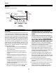
BALLAST LOCATION
Ballasts are located within the access panel that runs
the length of the rear of the case. See T-stat location
for placement, as they are in the same location.1
OPTIONAL
OPTIONAL
S
L
S
B
OPTIONAL
O
DY