IN-LINE POWER TUNING MODULE 2003-2004 Ford 6.0L Power Stroke® Super Duty F250/F350 & Excursion Part #41042 STEP-BY-STEP INSTALLATION INSTRUCTIONS Part #593 © 2004-2005 Hypertech, Inc. Revised 8.2.
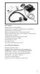
Kit Contains: Hypertech Power Tuning Module Wiring harness (connectors are marked for easy installation) Hypertech rotary switch assembly Hypertech mounting bracket (with module attached) Hypertech switch plate (cable, switch with knob, connector/wire) Small standard screwdriver Installation and operation manual (instructions) #10 Phillips-head screws (2 each) Retaining plugs (2 each) Tie-wraps (3 each) One tube of Boss RTV sealer (0.5 oz.
PLEASE READ BEFORE INSTALLING THE HYPERTECH IN-LINE POWER TUNING MODULE FOR THE 6.0L POWER STROKE Special instructions for the 6.0L Power Stroke 2003-2004 Ford Super Duty F250/F350 & Excursion SPECIAL NOTE: Power Stroke engines built before 9/29/03 must be updated to the newest calibration level (B27.9 or later) by an authorized Ford, Lincoln, or Mercury dealer. Ford Motor Company’s Technical Service Bulletin No.
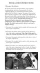
INSTALLATION INSTRUCTIONS I. Disconnect the batteries For specific instructions and precautionary steps regarding recommendations for battery disconnection, refer to the “Workshop Manual” for 2004 F250/350/450/550 vehicles, published by Ford Motor Company. This manual also contains battery-related precautionary steps regarding the Supplementary Restraint System (SRS) or air bag system. Failure to read and observe factory-recommended instructions may result in personal injury or property damage.
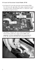
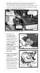
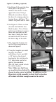
II. Locate the Powertrain Control Module (PCM) 6. See Figure B. Locate the powertrain control module (PCM). It is located on the right side of the engine compartment beside the primary battery. The PCM has three (3) connectors visible at the front, facing the battery. PCM with three (3) connectors Battery On Driver’s Side Figure B 7. See Figure C. Remove the center connector by pinching the lever lock (small tab or tongue in the middle of the connector, as shown) and pushing the lever away from the PCM.
8.See Figure D. The cable for the center connector lies in the space between the battery and the power steering fluid reservoir. Pull the connector and cable out from this space and re-route it so that the connector is between the power steering reservoir and the brake fluid reservoir. Power steering reservoir Center connector from PCM Brake fluid reservoir Figure D III. Inspecting the Hypertech cable 9.
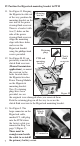
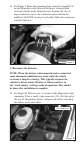
IV. Position the Hypertech mounting bracket & PTM 11. See Figure G. Keeping the Hypertech cable out of the way, position the mounting bracket on the rear side of the power steering fluid reservoir. There is a bracket with two (2) holes on this side of the power steering fluid reservoir. Align the mounting clips with these holes and secure the Hypertech bracket using the phillips-head screws provided. Mounting bracket Figure G Retaining plugs Clutch 12. See Figure H.
14. See Figure J. Route the remaining large connector (marked C4) on the Hypertech cable between the power steering fluid reservoir and the brake fluid reservoir. Position the two (2) large connectors (one is the connector removed from the middle of the PCM) to mate to each other. Mate the connectors and lock the lever. Figure J V. Reconnect the batteries NOTE: When the battery is disconnected and re-connected, some abnormal conditions may occur while the vehicle re-learns it adaptive strategy.
16. Re-install the battery cover onto the primary battery (driver’s side of the engine compartment). Make sure the cables around the cover are positioned such that the cover can be properly seated when installed. Connect the secondary battery positive cable (passenger side of the engine compartment). Connect the primary battery positive cable (driver’s side of the engine compartment). Connect the primary battery ground cable (driver’s side of the engine compartment).
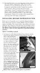
Option 2 (Drilling required) 1. See Figure N. Locate the fuse block panel. The panel is marked “Fuse Panel” in the upper left corner. Using a flathead screwdriver, loosen the four (4) retaining clips by turning them a half turn. Then remove the panel and set aside. 2. See Figure O. There are four (4) bolts that hold the fuse block in place. Use a 10mm socket or nut-driver to remove these bolts and pull out the fuse block. Swing the block out and to the left to access the lower edge of the dash. 3.
5. See Figure Q. On the Hypertech Rotary Power Selector switch, remove the mounting nut and washer from the switch shaft. There is one (1) additional ring on the switch shaft. The tab on this ring needs to remain in position number 4 when the switch is installed. From behind the panel, insert the switch into the panel hole. Line up the positioning tab into the small drilled hole. On the outside of the dash, place the provided Hypertech switch plate over the shaft.
10. See Figure S. From the engine side, pull the connector and cable through the firewall. Attach the connector to the main Hypertech cable by mating the two (2) 4-pin connectors. NOTE: The latch on the switch cable connector should snap over the tab on the mating connector. Figure S 11. Use the tie-wraps provided to secure the cable to existing cables, both inside beneath the dash and inside the engine compartment.
USER INSTRUCTIONS NOTE: Due to the adaptive learning strategy, the vehicle will need to be driven about 10 miles (or 15 minutes) on the 0 position (stock tuning) if the Power Tuning Module is ever removed and re-installed. Once you have completed all installation instructions, complete the following steps setting or changing power levels. 1. Set the rotary power selector switch to 0 (stock tuning). 2. Start the engine. Keep the transmission in PARK. 3.
What To Do Before Taking Your Vehicle In For Service If you take your vehicle to a dealer or mechanic for service, you must first restore the vehicle’s stock tuning. Hypertech recommends you temporarily remove the Power Tuning Module, even if the vehicle is restored to stock tuning. This assures the Hypertech Power Tuning Module will not interfere with any diagnostic procedures that may be performed during vehicle servicing. The Hypertech Power Tuning Module for the 20032004 6.
SPECIALTY AUTO PARTS CONSUMER’S BILL OF RIGHTS Your Rights To Personalize Your Vehicle Article 1: You have the Right to buy high-quality, reliable aftermarket performance and specialty parts, accessories, and styling options. Article 2: You have the Right to use high-quality aftermarket parts and know that your new vehicle warranty claims will be honored. In fact, your vehicle dealer may not reject a warranty claim simply because an aftermarket product is present.
Typical Performance Gains NOTE: All dynamometer tests are performed under controlled conditions. Results may vary, depending on the specific vehicle, altitude, temperature, fuel used, and various other conditions that affect vehicle performance. Power gains shown are specific to the vehicle tested and representative of the average gains verified. For a color, printable power graph of your particular application, check out our website at www.hypertech.com.
Hypertech Merchandise T- Shirts Available in long- or short-sleeve, these T-shirts are high-quality, printed in full-color and display the Hypertech Power Tuning logo. Available in sizes ranging from Small to XXX-large. Polo Shirts These short-sleeve polo shirts available in blue, red, white, or black are high-quality 100% cotton and have a full-color Hypertech logo embroidered on the left chest. Available in sizes ranging from medium to XX-large.
Notes