
Installation Instructions


Sehr geehrter Kunde,
Lesen Sie sich bitte die folgende Bedienungsanleitung sorgfältig vor der Inbetriebnahme durch, um durch
Bedienungsfehler bedingte Schäden zu vermeiden. Achten Sie insbesondere auf die
Sicherheitshinweise.
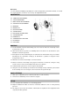
GERÄTEAUFBAU
1. VORDERES SCHUTZGITTER
2. VENTILATORFLÜGEL
3. GITTERBEFESTIGUNGSMUTTER
4. HINTERES SCHUTZGITTER
5. MOTORWELLE
6. MOTORGEHÄUSE
7. SCHWENKSCHALTER
8. STUFENSCHALTER
9. SCHALTKREISGEHÄUSE
10. FESTSTELLSCHRAUBE
11. OBERES STANDROHR
12. VERBINDUNGSSTÜCK
13. UNTERES STANDROHR
14. KREUZSOCKEL
ZUSAMMENBAU
1. Secure lower pipe with Pipe support to the hub of Cross Base with screw provided.
2. Extend upper pipe, insert the pipe connector through upper pipe onto lower pipe and tighten.
3. Attach the motor with switch compartment onto the upper pipe. Ensure the switch compartment
is pushed fully onto the upper pipe and secured with the screw provided.
4. Loosen Guard Mounting Nut from the Motor Housing.
5. Position Back Guard firmly to Motor Housing and then fasten by turning Guard Mounting Nut
clockwise tightly.
6. Push the Blade along Motor Shaft and fasten firmly with the Blade.
7. Hang the Front Guard to Back Guard with the position fixer provided at the rim of Guard, and
then fix together with clips provided.
OSCILLATION CONTROL
1. Befestigen Sie das untere Standrohr mit Rohrverbindungstück am Kreuzsockel.
2.
Verlängern Sie das obere Standrohr und fügen Sie es in das Rohrverbindungsstück. Ziehen Sie
es daraufhin fest.
3.
Befestigen Sie das Motorgehäuse und das Schaltkreisgehäuse am oberen Standrohr.
Vergewissern Sie sich, dass das Schaltkreisgehäuse vollständig auf das obere Standrohr
geschoben und mit der mitgelieferten Schraube befestigt wird.
4.
Lösen Sie die Befestigungsmutter des Schutzgitters vom Motorgehäuse.
5.
Positionieren Sie das hintere Schutzgitter fest am Motorgehäuse und befestigen Sie es, indem
Sie die Befestigungsmutter im Uhrzeigersinn festschrauben.
6.
Schieben Sie den Ventilatorflügel auf die Motorwelle und befestigen Sie ihn.