
Installation Manual

LII32-1
ICM
102
DELAY ON MAKE
HMPS00C
6333 Daedalus Drive, Cicero, N.Y. 13039
visit us on the web at: www.icmcontrols.com
800-365-5525
ICM CONTROLS
18-240 VAC/VDC, 2-Wire
Compressor Staging/
Startup Delay Timer
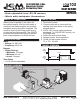
WIRING DIAGRAM
SPECIFICATIONS
Input
• Voltage: 18-240 VAC
• Frequency: 50-60 Hz
Output
• Output Ratings:
– Maximum: 1.5 amps
– Minimum: 40 mA
– Inrush: 15 amps
Time Delay
• .03-10 minutes adjustable
INSTALLATION
MODE OF OPERATION
When power is applied to the input, the
time delays begins. After the time delay is
complete, the load energizes and remains
energized as long as power is applied. The
control is reset by removing power during
or after the time delay period. The ICM102
provides thermostat interruption protection,
even in the presence of a trickle current.
•
Knob adjustable from .03-10 minutes
•
Works with anticipator thermostats
Y
R
C
T’STAT
Contactor
Compressor
Control
Transformer
Line
Voltage
TIMING DIAGRAM
0
V
Load
Voltage
0
V
Input
Voltage
Transfer
Load
Energized
Time Delay
Time
Time
1. Disconnect power.
2. Connect terminals in series with the
starting device as shown in the wiring
diagram below.
3. For 24 VAC circuits, apply control as
packaged. For 120/240 VAC circuits, cut
the jumper wire.
4. Select the desired time delay.
5. Reapply power, check operation.
6. Trickle current bypass resistor
T1 to T3 < 1K ohm.