INSTRUCTION MANUAL VHF AIR BAND TRANSCEIVER iA24 iA6 This device complies with Part 15 of the FCC Rules. Operation is subject to the condition that this device does not cause harmful interference.
SAFETY TRAINING INFORMATION Your Icom radio generates RF electromagnetic energy during transmit mode. This radio is designed for and classified as “Occupational Use Only”, meaning it must be used only during the course of employment by individuals aware of the hazards, and the ways to minimize such hazards. This radio is W ARN ING NOT intended for use by the “General Population” in an uncontrolled environment. This radio has been evaluated for compliance at the distance of 2.
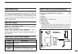
FOREWORD SUPPLIED ACCESSORIES Thank you for purchasing this Icom product. The IC-A24/A6 VHF AIR BAND TRANSCEIVER is designed and built with Icom’s state of the art technology and craftsmanship. With proper care this product should provide you with years of trouble-free operation. Accessories included with the transceiver: Qty. q Antenna .......................................................................... 1 w Belt clip ...........................................................................
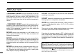
PRECAUTION R WARNING! NEVER hold the transceiver so that the DO NOT allow children to play with any radio equipment antenna is very close to, or touching exposed parts of the body, especially the face or eyes, while transmitting. The transceiver will perform best if the microphone is 5 to 10 cm (231⁄32 to 315⁄16 inch) away from the lips and the transceiver is vertical. containing a transmitter. R WARNING! NEVER operate the transceiver with a headset or other audio accessories at high volume levels.
TABLE OF CONTENTS SAFETY TRAINING INFORMATION ............................................... i FOREWORD ................................................................................... ii IMPORTANT .................................................................................... ii EXPLICIT DEFINITIONS ................................................................. ii SUPPLIED ACCESSORIES ............................................................ ii PRECAUTIONS....................................
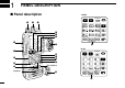
1 PANEL DESCRIPTION ■ Panel description IC-A24 WX-ALERT e r t y u i w o !7 IC-A6 q !7 !6 !5 Speaker WX-ALERT !0 !1 !2 !3 Microphone !4 !7 1
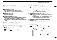
PANEL DESCRIPTION q BACKLIGHT SWITCH [LIGHT] Turns the backlight for display and keypad ON or OFF. w PTT SWITCH [PTT] (p. 9) Push and hold to transmit; release to receive. •“ ” appears on the function display while transmitting. e VOLUME [VOL] (p. 9) Adjusts the audio level. r TUNING DIAL [DIAL] (pgs. 8–12) ➥ Rotate [DIAL] to select the desired frequency, WX channel number, BANK number and memory channel. ➥ Rotate [DIAL] to set the squelch level and beep tone level. t ANTENNA CONNECTOR [ANT] (p.
1 PANEL DESCRIPTION !1 CLEAR KEY [CLR•DEL] (pgs. 8–17) ➥ Push to turn to the frequency mode, when memory channel, WX channel, 121.5 MHz, squelch level setting or beep tone setting is selected. ➥ Push , then push and hold [CLR•DEL] to delete a recall frequency data. ➥ Push to clear the entered comment of memory name while programming. ➥ Push to stop the scan function to turn to the frequency mode while the scan function is operating. !2 ANL KEY [ANL•SCAN] (pgs.
PANEL DESCRIPTION !7 DIGIT KEYS ➥ Input the specified digit during frequency input, memory channel selection, etc. ➥ In addition, each key has one or more secondary function after pushing as follows: Push , then push [0•BANK], and rotate [DIAL] to select the memory BANK number during the memory operation. (p. 12) Push , then push [1•DVOR] to select the DVOR display from the CDI display in NAV band. (p.
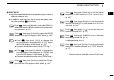
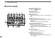
1 PANEL DESCRIPTION ■ Function display q FUNCTION INDICATOR (p. 2) Appears when is pushed. w TX INDICATOR (p. 9) Appears while transmitting. q w e r t y e RX INDICATOR (p. 9) Appears when receiving a signal or when the squelch opens. u !5 i !4 o !1 !3 !2 !1 !0 r DUPLEX INDICATOR (IC-A24 only) (p. 24) ➥“DUP” appears when the duplex function is activated in NAV mode. ➥“DUP” blinks while setting the duplex frequency. t LOW BATTERY INDICATOR (p.
PANEL DESCRIPTION 1 1 i TAG CHANNEL INDICATOR (p. 17) “ ” appears when the selected memory channel is set as a TAG channel. o MEMORY CHANNEL INDICATOR (pgs. 12–15) Shows the selected memory channel number. !0 MEMORY BANK NUMBER INDICATOR (p. 12) Shows the selected memory bank number. !4 COURSE INDICATORS (IC-A24 only) (p. 19) ➥ Indicates where your aircraft is located on a VOR radial in DVOR mode. ➥ Indicates where your desired course is located on a VOR radial in CDI mode.
2 ACCESSORY ATTACHMENT D Antenna CAUTION: DO NOT transmit without an antenna. Otherwise the transceiver may be damaged. D Belt clip Conveniently attaches to your belt. Attach the belt clip with the supplied screws as below. NOTE: Use the supplied screws only. Insert the supplied antenna into the antenna connector and screw down the antenna as shown below. Supplied screws D Battery pack replacement Before replacing the battery pack, push [PWR] for 2 sec. to turn the power OFF.
BASIC OPERATION 3 ■ Setting a frequency ■ Setting a squelch level ï Using keypad The transceiver has a noise squelch circuit to mute undesired noise while receiving no signal. q Push [SQL•WX-ALERT], then rotate [DIAL] to select the squelch level. q Push [PWR] for 2 sec. to turn power ON, then push [CLR•DEL] to select the frequency mode when memory CH number or WX CH number appears on the function display. w Push 5 appropriate digit keys to input the frequency. • Push [1•DVOR] as the 1st digit.
3 BASIC OPERATION ■ Receiving q Push [PWR] for 2 sec. to turn the power ON. w Push [SQL•WX-ALERT], then rotate [DIAL] counterclockwise to select the squelch level 0. e Rotate [VOL] to adjust the audio level. r Push [SQL•WX-ALERT], then rotate [DIAL] clockwise until the noise is muted. •“ ” indicator disappears. t Set the desired frequency using [DIAL] or keypad. y When a signal is received on the set frequency: •“ ” indicator appears. • Squelch opens and audio is emitted from the speaker.
BASIC OPERATION ■ Low battery indicator 3 D Deletes the stored recall channel Low battery indicator appears Low battery indicator when the battery power has decreased to a specified level. The attached battery pack requires recharging. q Push w Push or to select the deleting recall channel. , then push [CLR•DEL] for 2 sec. to delete it. • (e.g.) Deletes “r0” recall channel which is stored 120.450 MHz, and “r1” recall channel stores 123.450 MHz.
3 BASIC OPERATION ■ Setting weather alert function ■ Side tone function An NOAA broadcast station transmits a weather alert tone before any important weather announcements. When the weather alert function is turned ON, the transceiver detects the alert, and sounds a beep tone until the transceiver is operated. The previously selected (used) weather channel is checked any time during standby, or while scanning.
MEMORY OPERATION ■ Memory channel selection The transceiver has 200 memory channels for storage of often-used frequencies along with 6-character notes. q Push [MR•MW] to select memory mode. • Memory BANK number and memory CH number appears. 4 ■ Transferring memory contents This function transfers a memory channel’s contents into the frequency mode. This is useful when searching for signals around a memory channel’s frequency.
4 MEMORY OPERATION ■ Programming a memory channel • EXAMPLE: Programming WX-05* into memory BANK 3/ memory channel 9. Push q Push [CLR•DEL] to select the frequency mode, if necessary. w Select the desired frequency. • Push , then push [ENT•WX] to select a weather channel.* • Set the desired frequency or weather channel* using [DIAL] or keypad. e Push , then push [MR•MW] to enter the memory writ- or Push The transceiver has 200 (20 CH × 10 BANK) memory channels for storage of often-used frequencies.
MEMORY OPERATION 4 ■ Memory names ï Programming memory names Key Character Key The memory channel can display a 6-character names instead of the programmed frequency. 1 1, Q, Z 4 q Rotate [DIAL] to select the desired frequency in the frequency mode. w Push , then push [MR•MW] to program the contents into the selected memory channel. e Rotate [DIAL] to select the desired memory channel to be programmed. • Push , then push [0•BANK], and rotate [DIAL] to select the BANK number if desired.
4 MEMORY OPERATION • EXAMPLE: Programming 125.000 MHz into memory BANK 1/ memory channel 17 with “AIR-23” as a comment. Push Push Push Push Push Push Push Push Push Push NOTE: Push , then push [0•BANK], and then rotate [DIAL] to select the BANK number, if desired. Push [CLR•DEL] to exit the BANK selection mode.
SCAN OPERATION 5 ■ Scan types ■ COM band scan The U.S.A. version has 3 scan types to suit your needs. The non-U.S.A. versions have 2 scan types. q Push [CLR•DEL] to select the frequency mode. w Push [SQL•WX-ALERT], then rotate [DIAL] to set the squelch level to the point where noise is just muted. e Push , then push [ANL•SCAN] to start the scan. COM BAND SCAN 108.00 MHz 118.00 MHz Scan Repeatedly scans 136.975 all frequencies MHz over the entire COM band.
5 SCAN OPERATION ■ Weather channel scan (U.S.A. version only) q Push , then push [ENT•WX] to select a weather channel. w Set squelch to the point where noise is just muted. e Push , then push [ANL•SCAN] to start the scan. ■ “TAG” channel setting Memory and weather channels* can be specified to be skipped for the memory and weather channel* scans respectively. The “TAG” channel function is only available during scan operation. Push then • When a signal is received, the scan pauses until it disappears.
VOR NAVIGATION (IC-A24 ONLY) 6 ■ VOR indicators NAV BAND (108.00 117.975 MHz) COM BAND (118.00 136.975 MHz) DVOR MODE 5 6 To-from flag indicator Course indicator Push [F] then [1 DVOR]. Push [F] then [4 CDI].
6 VOR NAVIGATION (IC-A24 ONLY) ■ VOR functions D ‘TO’ or ‘FROM’ flag selection D To select the CDI mode To show the deviation between your flying course and the desired course, push , then push [4•CDI] to select the CDI mode. The to-from flag indicators indicate whether the VOR navigation information is based on a course leading to the VOR station or leading away from the VOR station. Push , then push [3•FROM] or [2•TO] to change the flag from ‘TO’ to ‘FROM’ or vice versa, respectively.
VOR NAVIGATION (IC-A24 ONLY) 6 ■ Flying to a VOR station r The course deviation needle appears when your aircraft is off course from the VOR station. The IC-A24 shows the deviation from a VOR station. • ‘Ω’ or ‘≈’ appears to indicate your aircraft is off course to the right or left, respectively. Correct your course until ‘Ω’ or ‘≈’ disappears. Each arrow represents a two-degree deviation. t Push , then push [1•DVOR] to exit the CDI mode.
6 VOR NAVIGATION (IC-A24 ONLY) 0 THE AIRCRAFT IS ON COURSE 123.65 VORTAC SEATTLE 116.8 Ch 115 SEA 300 290 280 270 N 330 340 350 310 320 Magnetic north 10 20 30 40 260 250 ir Des ding 60 230 70 VOR station 220 rse ou ed c 50 240 40 90 100 110 200 190 ea aft h 180 r Airc 80 210 170 130 160 150 140 120 0 THE AIRCRAFT IS OFF COURSE 123.65 VORTAC SEATTLE 116.8 Ch 115 SEA 300 290 280 270 NOTE: The course deviation indicator appears when the aircraft is off course.
VOR NAVIGATION (IC-A24 ONLY) 6 ■ Entering a desired course ■ Crosschecking position The IC-A24 shows not only the deviation from the VOR station but the deviation from the desired course. q Select 2 VOR stations on your aeronautical chart. w Push the keypad or rotate [DIAL] to set the frequency of one of the VOR station in the DVOR mode. q Push the keypad or rotate [DIAL] to set the frequency for the desired VOR station.
6 VOR NAVIGATION (IC-A24 ONLY) EXAMPLE: Entering the desired course bearing 65° to a VOR station. CROSSCHECKING POSITION VORTAC OLYMPIA 113.4 Ch 81 OLM 300 290 280 270 330 340 350 310 320 20 30 40 250 240 230 VOR station 220 90 100 110 200 190 180 170 130 160 150 140 120 330 340 350 310 320 10 20 30 40 260 50 250 60 240 70 230 80 210 23 300 290 280 270 10 260 123.65 VORTAC SEATTLE 116.
VOR NAVIGATION (IC-A24 ONLY) ■ Duplex operation (U.S.A. version only) The duplex function allows you to call a flight service station while receiving a VOR station. The duplex function requires frequency programming for the flight service station in advance. D Programming a duplex frequency q Push [CLR•DEL] to select the frequency mode. w Set a NAV band frequency using the tuning dial or keypad. • NAV band frequency range: 108.00–117.975 MHz , then push [5•DUP-W].
7 BATTERY PACKS ■ Battery charging ■ Battery cautions Prior to using the transceiver for the first time, the battery pack must be fully charged for optimum life and operation. CAUTION! NEVER CAUTION: To avoid damage to the transceiver, turn the power OFF while charging. • Recommended temperature range for charging: +10°C to +40°C (+50°F to +104°F) - The Li-Ion battery (optional) is functioning within –20°C to +60°C (–4°F to +140°F). • Use the supplied AC adapter on regular charging.
BATTERY PACKS D Regular charging q Attach the battery pack to the transceiver. w Be sure to turn the transceiver power OFF. e Connect the Wall charger or optional cable (CP-20) as shown below. r Charging the battery pack approx. 8 hours, depending on the remaining power condition. 7 ■ Optional battery case When using a battery case attached to the transceiver, install 6 × AA (LR6) size Alkaline batteries as illustrated below. q Remove the battery case from the transceiver.
7 BATTERY PACKS ■ Optional battery chargers D Rapid charging with the BC-119N+AD-101 D Rapid charging with the BC-121N+AD-101 The optional BC-119N provides rapid charging of battery packs. The following are additionally required. The optional BC-121N allows up to 6 battery packs to be charged simultaneously. The following are additionally required. • AD-101 charger adapter. • An AC adapter (may be supplied with BC-119N depending on versions) or the DC power cable (CP-20).
CLONING Cloning allows you to quickly and easily transfer the programmed data from one transceiver to another transceiver, or, data from PC to a transceiver using the optional CS-A24 cloning software. D Transceiver to transceiver cloning q Connect the OPC-474 CLONING CABLE with adapter plugs to [SP/MIC] jack of the master and slave transceivers. • The master transceiver is used to send data to the slave transceiver.
9 TROUBLESHOOTING If your transceiver seems to be malfunctioning, please check the following points before sending it to a service center. PROBLEM No power comes on. POSSIBLE CAUSE • The battery is exhausted. • Bad connection for the battery pack. • The CP-20’s fuse is blown. SOLUTION REF. pgs. 25–27 • Recharge the battery pack. • Check the connection to the transceiver. p. 7 • Check for the cause, then replace the p. 29 CP-20’s fuse to new one. No sound comes from • Squelch level is too deep.
SPECIFICATIONS D General • Frequency coverage (MHz): TX 118.000 to 136.975 RX 108.000 to 136.975*1 WX 161.650 to 163.275*2 *1: IC-A24 only, IC-A6; 118.000 to 136.975 MHz *2: U.S.A. version only. : 6K00A3E 16K0G3E (161.65 to 163.275 MHz) • Channel spacing : 25 kHz • Number of memory channels : 200 (20 CH × 10 BANKS) • Power supply requirement : Specified battery packs/case or 11.0 V DC at external DC jack • Usable temp. range : –10˚C to +60˚C (+14°F to +140°F) • Current drain : Tx 1.
11 OPTIONS D BATTERY CASE AND PACKS D BELT CLIPS • BP-208N BATTERY CASE Battery case for 6 × AA (LR6) Alkaline cells. • BP-209N Ni-Cd BATTERY PACK 7.2 V/1100 mAh Ni-Cd battery pack. • BP-210N Ni-MH BATTERY PACK 7.2 V/1650 mAh Ni-MH battery pack. • BP-211N Li-Ion BATTERY PACK 7.4 V/1800 mAh Li-Ion battery pack. • MB-103 BELT CLIP The same as supplied with the transceiver. • MB-86 SWIVEL BELT CLIP Belt clip for swivel type.
OPERATION GUIDE 32 Entering a desired course. VOR NAVIGATION (p. 22) , then push [4 CDI] to select CDI mode. ‘Ω’ or ‘ ≈’ appears on the function display when your aircraft is off the desired course. When your heading is correct, the ABSS function may be useful instead of course input. w Push set the frequency for the desired VOR station. Push , then push [2 TO] or [3 FROM] to change the tofrom flag. q Push keypad or rotate [DIAL] to n e Complete VOR NAVIGATION (p.
n Memory programming MEMORY OPERATION (p. 13) q Push [CLR DEL] to select the frequency mode or push , then push [ENT WX] to select WX CH* mode. WX CH.* w Select the desired frequency or , then push [MR MW] e Push to enter memory programming mode. “M”, BANK and memory numbers blink on the display. r Rotate [DIAL] (or push keypad) to select a desired memory CH number (0 to 19). Push then push [0 BANK], and rotate [DIAL] to select the BANK number if desired.
OPTIONAL HEADSET CONNECTION 13 D OPC-499 (HEADSET ADAPTER) connection When using a headset, such as those from the David Clark Co. via the OPC-499 HEADSET ADAPTOR adapter, the transceiver outputs your transmitted voice to the headset for monitoring. See “■ Side tone function” (p. 11) when setting the side tone level. PTT PTT switch Use a PTT switch with a 3.5 mm (1/8") diameter plug, if required.
A-6403D-1EX-e Printed in Japan © 2004–2005 Icom Inc.