INSTRUCTION MANUAL VHF FM REPEATER iFR5100 UHF FM REPEATER iFR6100
IMPORTANT R E A D T H I S I N S T RU C T I O N M A N UA L CAREFULLY before attempting to operate the repeater. SAVE THIS INSTRUCTION MANUAL– This manual contains important safety and operating instructions for the IC-FR5100/IC-FR6100 vhf/uhf fm repeaters. EXPLICIT DEFINITIONS WORD RWARNING CAUTION NOTE DEFINITION Personal injury, fire hazard or electric shock may occur. Equipment damage may occur. If disregarded, inconvenience only. No risk of personal injury, fire or electric shock.
FORWARD SUPPLIED ACCESSORIES Thank you for purchasing this Icom repeater. The IC-FR5100/IC-FR6100 vhf/uhf fm repeaters is designed and built with Icom’s state of the art technology and craftsmanship. With proper care, this product should provide you with years of trouble-free operation. The following accessories are supplied.
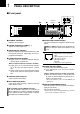
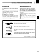
1 PANEL DESCRIPTION ■ Front panel q Function display w P0 P1 P2 o q INTERNAL SPEAKER Monitors received signals. w VOLUME CONTROL [VOLUME] (p. 7) Adjusts the audio output level. e SELECTOR DIAL [SELECT] Rotate to adjust the squelch threshold level, select the operating channel. (Depending on the preprogrammed condition.) t TRANSMIT INDICATOR [TX] Lights red while transmitting. y BUSY INDICATOR [BUSY] Lights green while receiving a signal or when the noise squelch is open.
PANEL DESCRIPTION 1 D Function display q w e ICOM r t Inc. y q SIGNAL STRENGTH INDICATOR Indicates relative signal strength level. r COMPANDER INDICATOR Appears when the compander function is activated. w LOW POWER INDICATOR Appears when low output power is selected. t SCRAMBLER/ENCRYPTION INDICATOR Appears when the voice scrambler/encryption function is activated. e AUDIBLE INDICATOR Appears when the channel is in the ‘audible’ (unmute) condition.
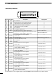
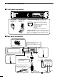
1 PANEL DESCRIPTION D Accessory connector !4 @5 q Pin No. !3 Description Pin Name Specification 1 NC No connection — 2 TXD Output terminal for serial communication data. — 3 RXD Input terminal for serial communication data. — 4 RTS Output terminal for request-to-send data. — 5 CTS Input terminal for clear-to-send data. — 6 NC No connection — 7 GND Serial/digital signal ground — 8 MOD IN 9 DISC OUT 10 EXT. D/A 11 VCC 12 EXT. A/D 13 NC 14 GND 15 EXT.
INSTALLATION AND CONNECTIONS 2 ■ Unpacking ■ Antenna connection After unpacking, immediately report any damage to the delivering carrier or dealer. Keep the shipping cartons. For radio communications, the antenna is a critical component, along with output power and sensitivity. Select antenna(s), such as a well-matched 50 ˘ antenna, and feedline. 1.5:1 or better of Voltage Standing Wave Ratio (VSWR) is recommended for desired band. Of course, the transmission line should be a coaxial cable.
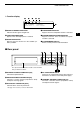
2 INSTALLATION AND CONNECTIONS ■ Front panel connection P0 HM-152 HAND MICROPHONE (optional) P1 P2 P3 P4 MICROPHONE CONNECTOR (Front panel view) SM-25 DESKTOP MICROPHONE (optional) q i q +8 V DC output (Max. 10 mA) w Output port for PC programming e NC r M PTT (Input port for TX control) t Microphone ground y Microphone input u Ground i Input port for PC programming CAUTION: DO NOT short pin 1 to ground as this can damage the internal 8 V regulator.
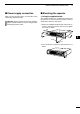
INSTALLATION AND CONNECTIONS ■ Power supply connection ■ Mounting the repeater Make sure the repeater’s power is turned OFF when connecting a DC power cable. D Using the supplied handle AUTION: Voltages greater than 16 V DC will damC age the repeater. Check the source voltage before connecting the power cable. 2 The supplied handles are available for mounting the repeater into a 19 inch rack. The handles can be installed to the repeater’s front panel.
3 OPERATION ■ Receiving and transmitting D Repeater operation Ask your dealer for details of the repeater’s programming. ➥W hen the power is turned ON, the [PWR] indicator lights green. (p. 1) ➥ The [TX] and [BUSY] indicators light simultaneously while transmitting/receiving a signal. • The [TX] indicator lights red. • The [BUSY] indicator lights green. NOTE: A power amplifier protector is built-in to the repeater.
MAINTENANCE 4 ■ Troubleshooting The following chart is designed to help correct problems which are not equipment malfunctions. PROBLEM If you are unable to locate the cause of a problem or solve it through the use of this chart, contact the nearest Icom Dealer or Service Center. POSSIBLE CAUSE SOLUTION Power does not come • DC power cable is improperly connected. on when [POWER] is pushed. • Fuse is blown. REF. • Re-connect the DC power cable correctly. pgs.
5 OPTIONS • SP-22 external speaker Compact and easy-to-install. Input impedance : 4 ˘ Max. input power : 5 W • HM-152 hand microphone • SM-25 desktop microphone • UR-FR5100/UR-FR6100 channel extension modules • UT-109R voice scrambler unit Non-rolling type (max. 32 codes). • UT-110R voice scrambler unit Rolling type (max. 1020 codes). * T he scrambler systems of the UT-109R and UT110R are not compatible with each other. Some options may not available in some countries. Please ask your dealer for details.
ABOUT CE 6 INSTALLATION NOTES • Compliance of base station transmitter installations with EN50385 The installation of this equipment and it’s associated antenna should be made in such a manner as to respect the EC recommended electromagnetic (EM) field exposure limits.
6 ABOUT CE • Typical installation example A UHF base station transmitter is to be installed on the roof of an office. The transmit power is 25 watts, there is 20 m of RG-213 coaxial cable and the antenna is vertically polarised dipole. The specification of the RG-213 cable gives a loss of 1.5 dB/10 m. There will be 3 dB loss for the 20 m length used.
ABOUT CE 6 DECLARATION OF CONFORMITY We Icom Inc. Japan 0168 1-1-32, Kamiminami, Hirano-ku Osaka 547-0003, Japan Declare on our sole responsibility that this equipment complies with the essential requirements of the Radio and Telecommunications Terminal Equipment Directive, 1999/5/EC, and that any applicable Essential Test Suite measurements have been performed. Düsseldorf 16th Apr.
< Intended Country of Use > AT FI IT PL GB RO BE FR LV PT IS TR CY DE LT SK LI HR A-6636H-1EU-w Printed in Japan © 2008 Icom Inc. Printed on recycle paper with soy ink.