8430/8830/8KE4/8KE8 Ethernet I/O Unit User’s Manual Version 1.0, January 2005 I-8430 I-8830 I-8KE4-G ICP DAS, Co., LTD I-8KE8-G www.icpdas.com 8430/8830/8KE4/8KE8 User’s manual, Jan 2005, Version 1.
8430/8830/8KE4/8KE8 Warranty All products manufactured by ICP DAS are under warranty regarding defective materials for a period of one year, starting from the date of delivery to the original purchaser. Warning ICP DAS assumes no liability for damages resulting from the use of this product. ICP DAS reserves the right to change this manual at any time without notice. The information furnished by ICP DAS is believed to be accurate and reliable.
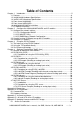
Table of Contents Chapter 1. Introduction......................................................................................................5 1.1 Features .................................................................................................................6 1.2 i-8430/i-8830 Hardware Specifications .................................................................10 1.3 i-8KE4/i-8KE8 Hardware Specifications................................................................12 1.
E.2 Updating MiniOS7 image ...................................................................................89 E.3 Download firmware ............................................................................................90 8430/8830/8KE4/8KE8 User’s manual, Jan 2005, Version 1.
Chapter 1. Introduction The i-8430,i-8830,i-8KE4 and i-8KE8 are Ethernet I/O units using DCON Protocol Firmware E10M_nnn.exe (*1). ICPDAS provides various I/O modules(*2) ,using such as analog input/output and digital input/output and counter modules which can be used in remote data acquisition and control application for environment monitoring, power management, factory automation, etc . via Ethernet communication. (*1): For detail of E10M_nnn.
1.1 Features Ethernet –based Data Acquisition I/O unit The i-8430,i-8830,i-8KE4 and i-8KE8 are Ethernet I/O unit. This feature allows Ethernet applications to access and control the remote I/O in industrial filed network. And E10M_nnn.exe or 8KE10.exe is the DCON firmware for the i-8430, i-8830, i-8KE4 and i-8KE8. Using this firmware, applications can be easily and directly developed using a TCP program, or via VxComm technology.
I/O configurable via the Ethernet The DCON Utility is used to configure I-7000, I-8000 and I-87K series I/O modules. It originally communicated with the I/O modules via the COM port. For I/O modules on the i-8430,i-8830,i-8KE4 and i-8KE8, using the VxComm technique to create a virtual COM port can let DCON Utility access the I/O modules via the Ethernet. For more details, please refer to Chapter 3.
z z z Support for new I/O modules The addition of new functions Bug fixes and revision There is a document (Revision.txt) that records the update information as follows: For more details, please refer to Appendix E: Updating the firmware and MiniOS7 image. Dual Bus design to supports i-8K and i-87K series I/O modules The 8430/8830/8KE4/8KE8 has two types of bus on its back plane. The first is a serial bus (RS-485 interface) for 87K I/O modules and the second is a parallel bus for 8K I/O modules.
Built-in Watchdog The built-in watchdog circuit will reset the CPU module if a failure occurs in either the hardware or software. If the application program does not refresh the watchdog timer within 0.8 sec, the watchdog circuit will initiate a reset of the CPU. Input Protection circuitry The protection circuitry on both the network and power supply protects the system from external signals such as main spikes and ambient electrical noise.
1.2 i-8430/i-8830 Hardware Specifications • CPU: 80188 or compatible 16-bits 40MHz • SRAM: 512KBytes • Flash ROM: 512KBytes 8 sectors, each sector has 64KBytes 100,000 erase/write cycles • EEPROM: 2K bytes 8 blocks, each block has 256Bytes 1,000,000 erase/write cycles • Built-in Watchdog Timer 0.8 seconds • Ethernet port: 10BaseT NE2000 compatible PC application use Ethernet to communicate with DCON Firmware. • COM0 (RS-232): TXD, RXD, GND, internal serial bus.
• Mounting mechanism pannel mounting and din-rail mounting • Power supply: 20W • Power requirement: 10 ~ 30 VDC • Power consumption: 3.9 W (for 8430) 5.1 W (for 8830) • Operating Environment: Operating Temp.: –25°C to +75°C. Storage Temp.: –30°C to +85°C Humidity: 5 ~ 95%,non-condensing • Dimension: 230 x 110 x 75.5 mm (for 8430) 354 x 110 x 75.5 mm (for 8830) For more detailed dimensions, please refer to “Appendix A:Dimensions”. 8430/8830/8KE4/8KE8 User’s manual, Jan 2005, Version 1.
1.3 i-8KE4/i-8KE8 Hardware Specifications • CPU: 80186-80 or compatible 16-bits 80MHz • SRAM: 512KBytes • Flash ROM: 512KBytes 8 sectors, each sector has 64KBytes 100,000 erase/write cycles • EEPROM: 2K bytes 8 blocks, each block has 256Bytes 1,000,000 erase/write cycles • NVRAM: 31 bytes unlimited erase/write cycles battery backup for 10 years • Real time clock: seconds, minutes, hours, days, month, year valid from 1980 to 2079 • Built-in Watchdog Timer 0.
• Mounting mechanism pannel mounting and din-rail mounting • Power supply: 20W • Power requirement: 10 ~ 30 VDC • Power consumption: 3.9 W (for 8KE4) 5.1 W (for 8KE8) • Operating Environment: Operating Temp.: –25°C to +75°C. Storage Temp.: –30°C to +85°C Humidity: 5 ~ 95%,non-condensing • Dimension: 230 x 110 x 75.5 mm (for 8KE4) 354 x 110 x 75.5 mm (for 8KE8) For more detailed dimensions, please refer to “Appendix A:Dimensions”. 8430/8830/8KE4/8KE8 User’s manual, Jan 2005, Version 1.
1.4 Front view of 8430/8830 8430: Small Man Machine Interface Power: 10~30VDC RS-232/485 (COM3) Initial pin RS-232 (COM1) 8830: 10M Ethernet port (COM2) Slot 0 Slot 1 Slot 2 Slot 3 Net ID. Small Man Machine Interface Power: 10~30VDC RS-232/485 (COM3) Initial pin RS-232 (COM1) Slot 0 10M Ethernet port (COM2) Slot 2 Slot 1 Slot 3 Slot 4 Slot 6 Slot 5 8430/8830/8KE4/8KE8 User’s manual, Jan 2005, Version 1.0, 8MS-002-10 Net ID.
Pin assignment of COM1 Port Pin assignment of COM3 Port 8430/8830/8KE4/8KE8 User’s manual, Jan 2005, Version 1.
1.
Pin assignment of COM1 Port 8430/8830/8KE4/8KE8 User’s manual, Jan 2005, Version 1.
1.6 8430/8830/8KE4/8KE8 installation Step1: Mount the I/O unit Method (a): using screw panel mounting Step1 (b): Mount the I/O unit (method b: DIN-rail mounting) Method (b): DIN-Rail mounting Frame Ground DIN-Rail Clips 8430/8830/8KE4/8KE8 User’s manual, Jan 2005, Version 1.
Step2: Attach power supply (10 ~ 30 VDC) The diagrams below show the basic wiring for the Ethernet I/O. 8430/8830/8KE4/8KE8 User’s manual, Jan 2005, Version 1.
Step3: Check the LED display The LED constantly shows IP address, Baud Rate, Data Bit Format ..etc as following sequences. 1.27.00 11111. The IP is 192.168.255.1 1. 192 2. 168 3. 255 4. 1 27: Free-sockets=27 00: No client connects to this 8000E 44444. 8. 821 COM8: data=8, odd parity, stop=1 2. 712 COM2: data=7, even parity, stop=2 1. 801 COM1: data=8, no parity, stop=1 33333. 22222. 1. 96 Baud Rate of COM1=9600 2.
1.7 I/O module installation Step1: Read the document at the following location For I-8000 series modules the files are located at: CD:\ Napdos\DCON\IO_Module\hw_dcon_on_8KUnit\8k ftp://ftp.icpdas.com/pub/cd/8000cd/napdos/dcon/io_module/hw_dcon_on_8kunit/8k/ For I-87K series modules the files are located at: CD:\ Napdos\DCON\IO_Module\hw_dcon_on_8KUnit\87k ftp://ftp.icpdas.com/pub/cd/8000cd/napdos/dcon/io_module/hw_dcon_on_8kunit/87k/ These *.
Pin assignment 8430/8830/8KE4/8KE8 User’s manual, Jan 2005, Version 1.
Wire Connection 8430/8830/8KE4/8KE8 User’s manual, Jan 2005, Version 1.
Step2: Connect the wire Step3: Insert the I/O module into the 8KE4/8KE8 8430/8830/8KE4/8KE8 User’s manual, Jan 2005, Version 1.
Chapter 2. modules Configure the 8430/8830/8KE4/8KE8 and I/O Before using the 8430/8830/8KE4/8KE8 and any I/O modules connected to it, the following settings must be configured: • Networking settings: IP, Mask, Gateway of 8430/8830/8KE4/8KE8 • Power on value of AO, DO modules • Safe value of AO, DO modules • Input range of AI modules • Noise filter of AI modules • Check sum of all communication protocol The most important thing at the beginning stage is the network setting.
3 Step4: Open the COM port and then click “Configure” to set the IP, Mask, Gateway to 8430/8830/8KE4/8KE8. 4.1 4.2 4.21 Step5: Exit the “Configure Wizard” and then restart the 8430/8830/8KE4/8KE8 for the new settings. 2.1.2 By MiniOS7 Utility The MiniOS7 Utility is used to download files and update the OS image to the 8430/8830/8KE4/8KE8. It can also be used to configure the network and COM port settings.
Step3: Run the MiniOS7 Utility and click “Configuration” Step4: Exit the MiniOS7 Utility and then restart the 8430/8830/8KE4/8KE8 for the new settings. 2.1.3 By SMMI Menu: Network Configuration L1 L2 L3 MODE UP DOWN POWER SET Step1: Accessing the SMMI menu The LEDs normally show system information. Pressing the “Mode” and Set buttons for more than 1.5 seconds will allow access to the SMMI menu. The LED menu has 2 levels.
Step2: The SMMI menu tree The SMMI menu is designed to allow the users to set the network settings (IP, Mask, Gateway) without requiring a host PC. Following is the SMMI menu tree. Cursor position 8430/8830/8KE4/8KE8 User’s manual, Jan 2005, Version 1.
Step3: Selection items that can be changed There are four items in the menu, and there are three items (IP, MASK, GATEWAY) that can be changed. When entering the LED menu, the initial status is at level 1 and the cursor position is at position 1 (IP) . L1 L2 L3 MODE UP DOWN POWER SET Only the “Mode” and “Set” buttons are available in this situation. By pressing the “Mode” button, the cursor can be moved with in same level.
2.2 Creating a virtual COM port to map the I/O modules Step1: Wire the 8430/8830/8KE4/8KE8 and configure its network settings (IP, Mask, Gateway) Step2: Install the VxComm driver appropriate for your PC (95/98/NT/2000/XP) CD:\Napdos\7188e\tcp\VxComm\Driver(PC)\ Step3: Run the VxComm Utility and connect to the 8430/8830/8KE4/8KE8 Step4: Map the “Port I/O” to a virtual COM port. Step5: Exit the VxComm Utility 2.
Step1: Wire the 8430/8830/8KE4/8KE8 and configure its network settings (IP, Mask, Gateway) Step2: Create a virtual COM port (for example: COM3) to map the I/O modules Step3: Install the DCON Utililty by running CD:\Napdos\Driver\DCON_Utility\Setup\setup.exe and then run it. 3.1 4.1 4.2 4.3 8430/8830/8KE4/8KE8 User’s manual, Jan 2005, Version 1.
Step4: Change the COM port to the virtual COM port. Note: for 8430/8830/8KE4/8KE8, the Baud Rate is unimportant. Any Baud Rate setting can be used. Step5: Search for the I/O modules on the 8430/8830/8KE4/8KE8. After the modules are found, individually click on them to configure them. 5.1 5.2 5.3 5.4 Note Note: All the 87K I/O modules that connected to 8430/8830/8KE4/8KE8 are rename to 80xx(87K) 8430/8830/8KE4/8KE8 User’s manual, Jan 2005, Version 1.
Chapter 3. Using the DCON Protocol 3.1 The feature of using DCON Protocol The DCON firmware which uses ASCII Command provided with the 8430/8830/8KE4/8KE8, is easy to use and most of application can be developed using toolkits supported by ICPDAS, such as DLL, ActivateX or OPC Server, which can shorten their development time. 8430/8830/8KE4/8KE8 User’s manual, Jan 2005, Version 1.
3.2 Using the TCP protocol directly Supports the DCON communication protocol on the Ethernet port. A TCP program can be used to develop Ethernet Applications to communicate with Ethernet port 9999 of the 8430/8830/8KE4/8KE8. The following steps show how to use VB Winsock component . Step 1. Connect to the Ethernet controller Step 2. Send command with cr Step 3. Receive data from Ethernet controller Step 4. Close connection. 8430/8830/8KE4/8KE8 User’s manual, Jan 2005, Version 1.
The result will be as below. This TCP application uses the DCON Protocol to communicate with Ethernet port 9999 of the i-8KE4 Ethernet I/O controller . The demo program can be found at CD:\Napdos\8000\843x883x\TCP\Xserver\Client\Common\VB5\Client4 Or on the internet at ftp://ftp.icpdas.com/pub/cd/8000cd/napdos/8000/843x883x/tcp/xserver/client/common/vb5/ client4/ 8430/8830/8KE4/8KE8 User’s manual, Jan 2005, Version 1.
3.3 Via VxComm technology VxComm (“Virtual Communication Port”) is a technique that allows a COM Port to be used to communicate with an ICPDAS Ethernet control unit. The Diagram below show how to use VxComm Utility to map PC’s COM Port to 8430/8830/8KE4/8KE8’s Ethernet I/O Port. 8430/8830/8KE4/8KE8 User’s manual, Jan 2005, Version 1.
Chapter 4. Software Development ToolKit (free) 4.1 Location of documents and software The location of all documents and software related to the 8430/8830/8KE4/8KE8 are shown in the following directory tree. The relevant file can quickly be located by referring to the tree. Various SDKs are provided for the DCON protocol, such as DLL, ActiveX, Labview driver, Indusoft driver, Linux driver, OPC server, etc.
The diagram below show the architecture of the SDK. Note: All the above SDKs are based on VxComm technology when using an Ethernet interface. 8430/8830/8KE4/8KE8 User’s manual, Jan 2005, Version 1.
4.2 DCON Utility (DOS) DCON Utility (DOS) DCON Utility (DOS version) Supported modules: i-7000/8000/87K series (with DCON protocol) Supported demos: C Supported OS: DOS File location: CD:\Napdos\Driver\DCON_DOS 4.2.1 Procedure for using the DCON Utility (DOS) Step 1: Read the basic and important documents Readme.txt: contains the basic and important information, including: • What is DCON Utility (DOS) • What files are installed on the PC Step 2: Read manuals for how to start DCON_DOS.
4.3 DCON DLL DCON DLL DLL library Supported modules: i-7000/8000/87K series (with DCON protocol) Supported demos: VB/VC/BCB/Delphi Supported OS: Windows 98/NT/2K/XP File location: CD:\Napdos\Driver\DCON_DLL 4.3.1 Procedure for using the DLL Step 1: Read the basic and important documents Readme.txt: contains most basic and important information, including: • • • • What is DCON DLL What files are installed on the PC The directory tree installed on the PC Demo list WhatsNew.
Step 2: Install the DCON DLL by executing: CD:\Napdos\Driver\DCON_DLL\Setup\setup.exe After installation, all related information can be found below Step3: Read manuals for how to start QuickStartManual.pdf: Explains how to develop your first program using the DLL. DCON_DLL.pdf explains the following details • • • • How to include the DLL in VB/VC/Delphi/BCB How to develop a program in VB/VC/Delphi/BCB Demo list Function descriptions and usage FAQ.pdf: Gives solutions to frequently asked questions.
4.3.2 VB Example (Reading an analog input value) The following is an example of reading analog values from an I-87017 inserted in slot 0 of an 8kE4/8KE8. Step 1: Wire the 8430/8830/8KE4/8KE8 and configure its network settings (IP, Mask, Gateway) Step 2: Run the VxComm Utility to create a virtual COM port (e.g. COM3) to map the 8430/8830/8KE4/8KE8 Step 3: Run the DCON Utility to configure the I/O modules Step 4: Run VB and create a new project (.exe project) Step 5: Add I7000.
Step 7: Write the program code VB Step 3 VB Step 1 VB Step 2 8430/8830/8KE4/8KE8 User’s manual, Jan 2005, Version 1.
Step 8: Run the project. 8430/8830/8KE4/8KE8 User’s manual, Jan 2005, Version 1.
4.4 DCON ActiveX DCON ActiveX ActiveX (ocx) component Supported modules: i-7000/8000/87K series (with DCON protocol) Supported demos: VB/VC/BCB/Delphi Supported OS: Windows 98/NT/2K/XP File location: CD:\Napdos\Driver\DCON_ActiveX 4.4.1 Procedure for using the ActiveX Step 1: Read most basic and important documents Readme.txt: contains the basic and important information, including: • • • • What is DCON ActiveX What files are installed on the PC The directory tree installed on the PC Demo list WhatsNew.
Step 2: Install the DCON ActiveX by executing: CD:\Napdos\Driver\DCON_ActiveX\Setup\setup.exe After installation, all related information can be found below Step 3: Read the manuals describing how to start InstallOCX.pdf: Explains how to install/uninstall the ActiveX (ocx) component in VB/VC/Delphi/BCB DCON_ActiveX.
Step 4: Run VB and create a new project (.exe project) Step 5: Add the ActiveX (ocx) component to the project 5.1 5.2 8430/8830/8KE4/8KE8 User’s manual, Jan 2005, Version 1.0, 8MS-002-10 5.
Step 6: Arrange all the components on the form Step 7: Write the program code VB Step 2 VB Step 3 VB Step 1 8430/8830/8KE4/8KE8 User’s manual, Jan 2005, Version 1.
Step 8: Run the project 8430/8830/8KE4/8KE8 User’s manual, Jan 2005, Version 1.
4.5 DCON LabVIEW DCON LabVIEW Bundled driver for LabVIEW Supported modules: i-7000/8000/87K series (with DCON protocol) Supported OS: Windows 98/NT/2K/XP File location: CD:\Napdos\Driver\DCON_Labview 4.5.1 Procedure for using DCON_LabVIEW Step 1: Install the DCON LabVIEW by executing: CD:\Napdos\Driver\ DCON_Labview\ DCON_Labview.exe After installation, the related information can be found as below: 8430/8830/8KE4/8KE8 User’s manual, Jan 2005, Version 1.
8000Demo: Demo programs for I-8000 I/O modules. 8000.llb: LabVIEW library contains all sub-vi for I-8000 I/O modules CallDLLinLabVIEW.pdf: Explains how to call a sub-vi of in LabVIEW. DCON_DLL.pdf: Descriptions of all sub-function in DCON_DLL 8430/8830/8KE4/8KE8 User’s manual, Jan 2005, Version 1.
Step 2: Create a new LabVIEW program. Refer the DCON_DLL.pdf about detail description of the sub-vi and where to select the sub-vi in various librarys of DCON_LabVIEW. Step3: Select the sub-vi form Functions Palette >> Select a VI… 8430/8830/8KE4/8KE8 User’s manual, Jan 2005, Version 1.
4.5.2 LabVIEW Example (Reading multi-channel analog Input value) Step4: Select the target *.lib file (LabVIEW library file) Step5: Select the desired sub-vi 8430/8830/8KE4/8KE8 User’s manual, Jan 2005, Version 1.
Step6 : Put the icon of selected sub-vi on Block Diagram, refer the “Help” >> “Show Help” or “DCON_DLL.pdf” in step1 for detail. Step7 : Draw the data flow of sub-vi. 4.5.2 LabVIEW Demo Program (Reading multi-channel analog input value) Step 1: Select the appropriate demo program by the name according with module’s function. 8430/8830/8KE4/8KE8 User’s manual, Jan 2005, Version 1.
Step2: Set the parameters 2.1 2.2 You could also refer the “Help”>>”Show Context Help” for getting the simple description of those parameters. Step3: Run the demo. 8430/8830/8KE4/8KE8 User’s manual, Jan 2005, Version 1.
4.6 DCON Indusoft DCON Indusoft Bundled driver for Indusoft Supported Module: i-7000/8000/87K series (with DCON protocol) Supported OS: Windows 98/NT/2K/XP/CE File location: CD:\Napdos\Driver\DCON_Indusoft 4.6.1 Procedure for using the Indusoft bundled driver Step 1: Read the basic and important documents Readme.txt: contains the basic and important information, including: • Files on the shipped CD Reversion.
Step 3: Run the DCON Utility to configure the I/O modules Step 4: Run Indusoft and create a new project Step 5: Include the DCON driver 5.1 5.2 5.3 5.4 8430/8830/8KE4/8KE8 User’s manual, Jan 2005, Version 1.
Step 6: Configure the DCON driver 6.2 6.1 6.3 8430/8830/8KE4/8KE8 User’s manual, Jan 2005, Version 1.
Step7: Insert tags to connect to I/O modules The address format is [Address : ModuleID : Slot : Channel] 7.1 7.2 Step8: Arrange all the components on the form 8430/8830/8KE4/8KE8 User’s manual, Jan 2005, Version 1.
Step9: Double click the text box to assign a tag to it 9.1 9.2 Step10: Run the project 8430/8830/8KE4/8KE8 User’s manual, Jan 2005, Version 1.
4.7 NAP OPC Server NAP OPC server OPC Server Supported module: i-7000/8000/87K series (with DCON protocol) Modbus embedded controller ISaGRAF embedded controller Supported OS: Windows 98/NT/2K/XP/CE File location: CD:\Napdos\NapOPCSvr 4.7.1 Introduction OPC (OLE for Process Control) is the first standard resulting from the collaboration of a number of leading worldwide automation suppliers working in cooperation with Microsoft.
4.7.2 Procedure for using the OPC server Step 1: Read the basic and important documents Readme.txt: contains the basic and important information, including • Files on the shipped CD Reversion.txt: contains the reversion information, including • Bugs fixed • New modules supported Step 2: Install the OPC server by executing CD:\Napdos\NapOPCSvr\NapOPCServer.exe Note: If there is an older version of Nap OPC Server installed on the PC, It must be uninstalled before installing the new version.
4.7.3 OPC Server Example (Reading an analog input value) The following is an example of reading analog values from an I-87017 inserted in slot 0 of an 8430/8830/8KE4/8KE8. Step 1: Wire the8430/8830/8KE4/8KE8 and configure its network settings (IP, Mask, Gateway) Step 2: Run the VxComm Utility to create a virtual COM port (e.g. COM3) to map the 8430/8830/8KE4/8KE8 Step 3: Run the DCON Utility to configure the I/O modules 8430/8830/8KE4/8KE8 User’s manual, Jan 2005, Version 1.
Step 4: Run the OPC server to search for I/O modules on COM3 4.1 4.2 4.4 4.3 8430/8830/8KE4/8KE8 User’s manual, Jan 2005, Version 1.
Step 5: Save the configuration and close the OPC Server Step 6: Run SCADA software to connect to the OPC Server The OPC Server user’s manual lists the procedures for the following SCADA software: • Labview • National • WIZCON • iFix • Indusoft • Citect Please refer to “Chapter 4 Connecting to the OPC Server” for more details. 8430/8830/8KE4/8KE8 User’s manual, Jan 2005, Version 1.
Appendix A: Dimensions i-8430 : Back View Side View Top View +VS Input: 10~30VDC GND INIT* Initialize INIT*COM Ethernet 10 BaseT Front View 8430/8830/8KE4/8KE8 User’s manual, Jan 2005, Version 1.
i-8830: Back View Side View Top View +VS Input: 10~30VDC GND INIT* Initialize INIT*COM Ethernet 10 BaseT Front View 8430/8830/8KE4/8KE8 User’s manual, Jan 2005, Version 1.
i-8KE4 : Back View Side View Top View +VS Input: 10~30VDC GND INIT* Initialize INIT*COM Ethernet 10 BaseT Front View 8430/8830/8KE4/8KE8 User’s manual, Jan 2005, Version 1.
i-8KE8: Back View Side View Top View +VS Input: 10~30VDC GND INIT* Initialize INIT*COM Ethernet 10 BaseT Front View 8430/8830/8KE4/8KE8 User’s manual, Jan 2005, Version 1.
Appendix B: DCON protocol The DCON protocol is a request/reply communication protocol for the I-7000/8000/87K series I/O modules, and uses a simple ASCII format such as $AAN, $AASi6, #AAN, #AASiCj,..., etc.
B.1 Command Set The full DCON protocol command sets for i-8000 series’ can be found in CD:\Napdos\DCON\IO_Module\ ftp://ftp.icpdas.
#AASi Command Description Syntax #AASi Reads the analog input or counter/frequency module data for all channels from specified slot in the I-8000 unit. #AASi[CHK](cr) # A delimiter character AA A 2-character HEX module address for the specified I-8000 system ,ranging from 01 to FFh Si The specified slot number.
#AASiCj Command Description Syntax Example Notes: #AASiCj Reads the analog input or counter/frequency module data from specified slot and the specified channel in the I-8000 unit. #AASiCj[CHK](cr) # A delimiter character AA A 2-character HEX module address for the specified I-8000 unit, ranging from 01 to FFh Si The specified slot number. i = 0 to 3 (4 slots) or i = 0 to 7 (8 slots) Cj specified channel number.
#AASiCj Command Description Syntax Example 1: Example 2: #AASiCj(data) Sets the analog voltage output module data from the specified slot and channel in the I-8000 unit. The data format is in engineering units only. #AASiCj(data)[CHK](cr) # A delimiter character AA A 2-character HEX module address for the specified I-8000 unit ,ranging from 01 to FFh Si The specified slot number. i = 0 to 3(4 slots) or i = 0 to 7(8 slots) Cj The specified channel number.
$AASi6 Command $AASi6 Description Read back the Digital Output module value and read the Digital Input module value of a specified slot in the I-8000 unit. Syntax $AASi6[CHK](cr) $ A delimiter character AA A 2-character HEX module address for the specified I-8000 unit, ranging from 01 to FFh Si The specified slot number.
# AASi00(data) For multiple channels DO output #AASi00(data) Command Description Sends the value to the digital output module for multiple channels output of a specified slot in the I-8000 unit #AASi00(data)[CHK](cr) Syntax $ A delimiter character AA A 2-character HEX module address for the specified I-8000 unit ,ranging from 01 to FFh Si The specified slot number.
This example is for a 16-channel digital output module. The Digital output Module in slot 3 and channels 0,2,4,6 (55h), 9, 11, 13, 15 (AAh) of the I-8000 unit at address 01h will be set to ON. Channels 1, 3, 5, 7, 8, 10, 12, 14 are set to OFF. This example just for output module channel number is greater than 8 and less then or equal to 16. 8430/8830/8KE4/8KE8 User’s manual, Jan 2005, Version 1.
# AASiBjDS For single channel DO output #AASiBjDs Command Description This command sends the value to the digital output module of the specified channel and slot of the I-8000 unit. This command is only for output modules which the channel number is less than or equal to 16. #AASi1BDs[CHK](cr) Syntax $ A delimiter character AA A 2-character HEX module address for the specified I-8000 unit ,ranging from 01 to FFh Si The specified slot number.
Description This example is for a single channel. The Digital output Module in slot 3 and channel 10 (0Ah) of the I-8000 unit at address 01h will be set to OFF. This example is only for output modules where the channel number is less than or equal to 16. The table below show to use command #AASiBjs to set 16-channel digital output module of the specified channel and slot of the I-8000 unit.
B.2 Hardware interface The hardware interface used to access the I-7000/8000/87K series I/O modules can be divided into the following: z RS-232: I-8000 MCU with DCON_nnn.exe or 8K232.exe firmware. Baud Rate: 1200, 2400, 4800, 9600, 19200, 38400, 57600, 115200bps. Data format is: 1 start bit, 8 data bits, non-parity, 1 stop bit z RS-485: I-7000/87K series I/O modules and I-8000 MCU with DCON_nnn.exe (or 8K485.exe ) firmware Baud Rate: 1200, 2400, 4800, 9600, 19200, 38400, 57600, 115200bps.
Appendix C: VxComm technique VxComm (“Virtual Communication Port”) is a technique that allows access to remote I/O slots or RS-232 ports. There are two types of software interfaces that can be used to access remote I/O modules and the COM ports of the 7188E/8000E series the first is serial port interface and the second is the TCP/IP interface. For the serial port interface, we provide a VxComm driver for Windows OS.
The two application architectures are shown as below: 8430/8830/8KE4/8KE8 User’s manual, Jan 2005, Version 1.
Appendix D: i-8K and i-87K series I/O modules The DCON firmware (DCON_nnn.exe and E10M_nnn.exe) supports both 8K and 87K series I/O modules. The two series I/O modules can be plug in same I-8000 MCU. The modules for DI, DO, DIO, AI, AO and Counter/Frequency purpose are supported. Other modules such as multi-serial port (8112, 8144, 8142, 8144), MMC(8073), motion (8090, 8091) are not supported. The file in the shipped CD lists details. CD:\Napdos\Driver\DCON_Utility\DCON_Utility_Module_List.
The differences between I-8000 and I-87K series I/O modules are Item i-8000 series Microprocessor No Communication interface Parallel bus (Note1) Communication speed Fast DI latched function No Counter input (for digital input module) No Power on value Yes (Note3) Safe value Yes (Note3) Host watchdog Yes Module watchdog No Programmable slew-rate for AO module No i-87K series Yes (8051) Serial bus (Note2) Slow Yes Yes (100 Hz) Yes Yes Yes Yes Yes Note: 1.
Appendix E: Updating firmware and MiniOS7 image In following situations, we release the new version firmware and MiniOS7 image. z z z Supporting new I/O modules Adding new functions Fixing bugs The tool to update firmware and MiniOS7 image is MiniOS7 Utility. File location of MiniOS7 Utility CD:\Napdos\MiniOS7\Utility\MiniOS7_Utility\MiniOS7_Utility.exe or ftp://ftp.icpdas.com/pub/cd/8000cd/napdos/minios7/utility/minios7_utility/ 8430/8830/8KE4/8KE8 User’s manual, Jan 2005, Version 1.
E.1 Access the controller Please follow the steps to do the updating procedure. Step1: Install MiniOS7 Utility Step2: Use CA-0915 to connect 8430/8830/8KE4/8KE8 to COM1/2 of the host PC. Step3: Short Init* and Init*COM. Step4: Power off and then power on the 8430/8830/8KE4/8KE8. The CPU doesn’t run the autoexec.bat while power on stage. 841X/881X 4 3 POWER SUPPLY Power: 10~ +10V~30VDC 30 VDC 2 RS-232 DEVICE CA0915 CA-0915 8430/8830/8KE4/8KE8 User’s manual, Jan 2005, Version 1.
Step5: Run MiniOS7 Utility Step6: Select the COM port of the host PC. 6.1 6.2 8430/8830/8KE4/8KE8 User’s manual, Jan 2005, Version 1.
After opening the COM port, the MiniOS7 Utility will show informations as below: i. MiniOS7 image version of the 8430/8830/8KE4/8KE8. ii. Files in the Flash ROM 2. List files in the Flash ROM 1. MiniOS7 image information 8430/8830/8KE4/8KE8 User’s manual, Jan 2005, Version 1.
E.2 Updating MiniOS7 image After setup MiniOS7 Utility and initial the 8430/8830/8KE4/8KE8. please follow the steps to do the updating MiniOS7 image. Step1: Click and select the file to update MiniOS7. 8430/8830: CD:\Napdos\DCON\8430_8830\OS_Image\40MHz\8K040330.img) ftp://ftp.icpdas.com/pub/cd/8000cd/napdos/dcon/8430_8830/os_image/40mhz/8k040330.img 8KE4/8KE8: : CD:\Napdos\DCON\8KE4_8KE8\OS_Image\8e040420.img) ftp://ftp.icpdas.com.tw/pub/cd/8000cd/napdos/dcon/8ke4_8ke8/os_image/8e040420.img 1.
E.3 Download firmware Please follow the steps to download the firmware to the Flash ROM. Step1: Delete all files in the Flash ROM. Step2: Select the firmware files and autoexec.bat and click files into the Flash ROM to download the 1 2.1 2.2 Step3: Disconnect Init* and Init*COM 4 3 Step4: Run the firmware Method 1: Power off and then power on the 8430/8830/8KE4/8KE8. The CPU will run the autoexec.bat in the Flash ROM. Method 2: Click to run the firmware.