installation and servicing icos (V3 Flue System) Your Ideal installation and servicing guide For details of document amendments, refer to page 3 HE12, HE15, HE18, HE24 For users guide see reverse of book When replacing any part on this appliance, use only spare parts that you can be assured conform to the safety and performance specification that we require. Do not use reconditioned or copy parts that have not been clearly authorised by Ideal Boilers.
icos - Installation & Servicing
DOCUMENT AMENDMENTS Relevant Installation changes implemented in this book from Mod Level ......................... A03 to A04 (Apr 08) • Page 15, Frame 11 - Unpacking Change to boiler contents, wall mounting template now mounted on internal packaging. • Page 15, Frame 12 - Packaging Removal Wall mounting template now mounted on internal packaging, frame changed to reflect this.
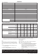
GENERAL Table 1 - Boiler Data Boiler Size HE 12, HE 15, HE 18, HE 24 2H-G20-20 mbar Rc1/2 (1/2" BSP Female) Gas supply type and connection Injector size Stereomatic 5.6mm dia. (HE 12 5.8mm dia). Flow connection 22mm copper Return connection 22mm copper Flue terminal diameter mm (in.) 100 (4) Maximum static water head m (ft.) 30.5 (100) Minimum static water head m (ft.) 0.45 (1.5) Electrical supply 230 V ~ 50 Hz Boiler power consumption 38W Fuse rating External: 3A Internal: T3.
GENERAL icos CONTENTS Natural Gas only Boiler size HE12 HE15 HE18 HE24 G.C. Appliance No. Benchmark No. PI No. 41 397 95 41 397 83 41 397 84 41 397 85 87 BP 34 87 BP 34 87 BP 34 87 BP 34 Destination Countries: GB, IE Air Supply ....................................................................... 9 Benchmark Commissioning Checklist ..................... 54 Boiler Clearances ......................................................... 6 Boiler Exploded Diagram .......................................
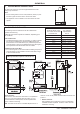
GENERAL 1 BOILER WATER CONNECTIONS The boiler flow and return pipes are supplied fitted to the boiler ready for top connection Notes. a. For the heating loads in excess of 60,000 Btu/h, 28mm (1") flow and return pipes should be used to and from the boiler. b. This appliance is NOT suitable for use with a direct hot water cylinder. 2 BOILER CLEARANCES all dimensions in mm (in.
GENERAL INTRODUCTION The icos range of boilers are a fully automatically controlled, wall mounted, low water content, balanced flue, fanned, condensing gas boiler. It has full modulating central heating outputs of : HE12 9.3 kW (32,000 Btu/h) to 12.0 kW (41,000 Btu/h). HE15 8.8 kW (30,000 Btu/h) to 14.6 kW (50,000 Btu/h). HE18 8.8 kW (30,000 Btu/h) to 17.6 kW (60,000 Btu/h). HE24 8.8 kW (30,000 Btu/h) to 23.4 kW (80,000 Btu/h).
GENERAL SAFE HANDLING OF SUBSTANCES Care should be taken when handling the boiler insulation panels, which can cause irritation to the skin. No asbestos, mercury or CFCs are included in any part of the boiler or its manufacture. LOCATION OF BOILER The boiler must be installed on a flat and vertical wall, capable of adequately supporting the weight of the boiler and any ancillary equipment.
GENERAL 6. The air inlet/products outlet duct and the terminal of the boiler MUST NOT be closer than 25mm (1") to combustible material. Detailed recommendations on the protection of combustible material are given in BS.5440-1:2000. In IE refer to I.S.813:2002. IMPORTANT.
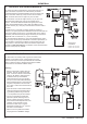
GENERAL 3 OPEN VENT SYSTEM REQUIREMENTS The system should be vented directly off the boiler flow pipe, as close to the boiler as possible. The cold feed entry should be inverted and MUST be positioned between the pump and the vent, and not more than 150mm (6") away from the vent connection. Note. Combined feed and vent pipes may also be fitted. There should be a minimum height 450mm (18") of open vent above the cistern water level. If this is not possible refer to Frame 5.
GENERAL 5 LOW HEAD AND LARGE SYSTEMS WITH EXTENSIVE PIPE RUNS - OPEN VENT This arrangement is useful for large systems where radiators at the extremities are difficult to vent. This can lead to pumping over with conventional feed and vent arrangements. The following conditions MUST be observed: 1. The top of the automatic air vent must be below the cold water level. 2. The static water level (cold) must be at least 200mm above the top of the horizontal flow pipe, fitted as shown.
GENERAL 7 SEALED SYSTEM REQUIREMENTS - continued 4. Expansion Vessel a. A diaphragm type expansion vessel must be connected to a point close to the inlet side of the pump, the connecting pipe being not less than 15 mm (1/2" nominal) size and not incorporating valves of any sort. b. The vessel capacity must be adequate to accept the expansion of the system water when heated to 110oC (230oF). c. The charge pressure must not be less than the static water head above the vessel.
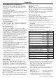
GENERAL 8 SEALED SYSTEM REQUIREMENTS - continued Safety valve setting 3.0 bar Vessel charge and initial system pressure 0.5 bar 2.5 bar 1.0 bar 1.5 bar Total water content of system litres 0.5 bar 1.0 bar 2.0 bar 1.5 bar 0.5 bar 1.0 bar Expansion vessel volume litres 25 2.1 2.7 3.9 2.3 3.3 5.9 2.8 5.0 50 4.2 5.4 7.8 4.7 6.7 11.8 5.6 10.0 75 6.3 8.2 11.7 7.0 10.0 17.7 8.4 15.0 100 8.3 10.9 15.6 9.4 13.4 23.7 11.3 20.0 125 10.4 13.6 19.5 11.7 16.7 29.
10 BOILER ASSEMBLY - Exploded view 40 94 nm8744 INSTALLATION INSTALLATION 23. Control thermistor. 24. Overheat thermostat. 25. Ignition electrode. LEGEND 15. Venturi assy. 26. Flame detection electrode. 16. Fan assy. 32. 'S' trap 17. Gas pipe assy. 33. Control assy. 19. Gas control valve assy. 40. Spark generator 20. Fan bracket assy. 44. Wall mounting plate. 13. Heat exchanger 21. Orifice plate. 53. Turret gasket kit. 14. Injector & housing 22. Flue thermistor. 94. Ignition lead 1.
11 INSTALLATION INSTALLATION UNPACKING The boiler is supplied fully assembled in one Pack A, together with a telescopic flue assembly for lengths up to 595mm, rear or side flue outlet, in Pack B. A Unpack and check the contents.
13 FRONT AND BOTTOM PANEL REMOVAL 3 1. To remove the front panel remove the 2 screws from the bottom panel. 2. Lift the panel up and off the top pegs. 3. To remove the bottom panel remove the 2 screws. 1 4. Pull the RH side of the panel down. Slide it to the right and withdraw. 14 DETERMINING THE FLUE LENGTH AND FLUE PACKS REQUIRED IMPORTANT. The boiler MUST be installed in a vertical position. Dimension X - Wall thickness. Dimension L - Wall thickness plus boiler spacing.
INSTALLATION 15 FLUE ASSEMBLY - Exploded View An optional flue duct extension kit is required for wall thicknesses greater than : Side 395mm Rear 435mm LEGEND 1. Duct assembly. 1 2. Flue turret. 3. Turret gasket. 4. M5 x 10 pozi screw. 5. Turret clamp. Rear flue arrangement shown nm8752 16 WALL MOUNTING TEMPLATE The wall mounting template is located on the internal top protective packaging. Extended centre line 155 Note.
INSTALLATION 17 PREPARING THE WALL IMPORTANT. Ensure that, during the cutting operation, masonry falling outside of the building does not cause damage or personal injury. 1. Cut the flue hole (preferably with a 5" core boring tool), ensuring that the hole is square to the wall. Both wall faces immediately around the cut hole should be flat. 2. Drill 3 holes with a 7.5mm / 8mm masonry drill and insert the plastic plugs provided, for the wall mounting plate and the jacking screw plate. Note.
INSTALLATION 20 FLUE EXTENSION DUCTS - For total flue lengths greater than 595mm Pack D Flue extension duct kit contents. Flue support cutting aid (shown folded up) Extension duct & clamp 1.0m (39") long Wall plugs - 4 off nm8732 Flue duct support No. 10 x2" wood screw - 4 off 21 FLUE EXTENSION DUCTS - continued Flue length Use a maximum of 6m extended flue ONLY Extension flue General arrangement 1. A maximum of 6 extension ducts (one suitably cut) plus the standard flue duct may be used together.
23 CONDENSATE DRAIN Refer also to the British Gas document: 'Guidance Notes for the Installation of Domestic Gas Condensing Boilers' (1989). The condensate drain provided on the boiler must be connected to a drainage point, preferably within the building. Ensure that the condensate trap is full of water before commissioning the boiler. Refer to Frame 27. The routing of the drain must be made to allow a minimum fall of 1 in 20 away from the boiler, throughout its length.
INSTALLATION INSTALLATION 25 CONDENSATE PIPE TERMINATION CONFIGURATIONS . . . continued 3. INTERNAL CONNECTION TO SOIL AND VENT STACK Termination into a down pipe can take place providing it can be confirmed that the down pipe is part of a combined waste and rain water system. * Make connection to SVP using a solvent welded saddle BOILER Air Break cla9253 4. TERMINATION TO SOAK AWAY External wall Termination to Soak away BOILER cla7774 minimum 500mm Ground Level 5.
INSTALLATION INSTALLATION 26 MOUNTING THE BOILER 1 1. Lift the boiler onto the wall mounting plate, as shown. 2. Check the boiler alignment using a spirit level and adjust as necessary with the jacking screw. 3. Align the hole in the jacking plate with the predrilled hole in the wall and fix in position with the No.10 x 2" screw provided. 4. Fit condensate union connection 27 CONNECTING THE FLUE TO THE BOILER 2 Note.
INSTALLATION 28 FITTING THE OPTIONAL ROOF FLUE KIT (Flat or Pitched) Note. A flat or pitched roof flashing plate (not supplied) is required before proceeding with the installation of this kit. This kit is suitable for both flat and pitched roof terminations, using a concentric flue to run vertically from the top of the boiler and terminating above roof level. Connection to the top of the boiler is made using both a separately supplied vertical connector and a 80/125 adaptor.
INSTALLATION 30 FLUE TERMINAL POSITION The terminal should be positioned so that products of combustion can safely disperse at all times. Pluming may occur at the termination so, where possible, terminal positions where this could cause a nuisance should be avoided.
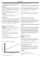
INSTALLATION 31 FLUE ARRANGEMENT Note. The equivalent flue length resistance of the elbow kits are: 90o elbow kit = 1m rf8737 FLUE OUTLET rf8738 45o elbow kit = 0.
INSTALLATION 32 ASSEMBLING THE ROOF FLUE KIT Determine the correct height that the flue should terminate above the roof. If after calculating or measuring the overall flue height from the top of the boiler, it is necessary to cut both pipes of assembly A, then ensure they are cut equally leaving the inner flue tube longer than the outer air tube as supplied. 1. Position the roof flashing plate (supplied separately) over the hole cut in the roof and insert flue terminal from the roof end. MAX LENGTH: 7.
INSTALLATION INSTALLATION 33 GAS CONNECTION IMPORTANT. The gas service cock is sealed with a non-metallic fibre washer seal so must not be overheated when making capillary connections. Refer to Frame 2 for details of the position of the gas connection. N.B. The principle of the 1:1 gas valve ensures that the icos HE range is able to deliver it’s full output at inlet pressures down to 14mb.
36 INTERNAL WIRING A pictorial wiring diagram is shown in Frame 37. The mains lead connector is pre-fitted. This must be removed to allow wiring. 1. Route the mains cable into the bottom LHS rear of the casing. If using the stand-off kit then route through the grommet. 2. Wire a permanent live supply into the 5-way remote plug terminals L3, N and . IMPORTANT. A permanent live is ESSENTIAL in order for the advanced diagnostic controls to function correctly. 3.
37 PICTORIAL WIRING DIAGRAM pk y bk b r y/g bk Fan Flue thermistor bk y/g or Overheat thermostat or y y Gas valve r Flow control thermistor r Chassis earth y/g b y/g bk LEGEND b - blue bk - black br - brown gy - grey or - orange pk - pink r - red v - violet w - white y - yellow y/g - yellow/green INSTALLATION INSTALLATION MAINS SUPPLY 230V 50Hz y/g Spark generator bk Permanent black link y/g y/g y/g br User control and display b Ferrite bk br b b or Fused at 3.
INSTALLATION INSTALLATION 39 EXTERNAL ELECTRICAL CONTROLS Wiring external to the boiler MUST be in accordance with the current I.E.E. (BS.7671) Wiring Regulations and any local regulations. For IE reference should be made to the current ETCI rules for electrical installations. The fuse should be 3A. Room Thermostat If the thermostat has a neutral connection use it. (It provides for more energy efficient operation by reducing switching temperature differentials.
INSTALLATION INSTALLATION 41 INITIAL LIGHTING 1. Check that the system has been filled and that the boiler is not air locked. Note. It is important the burner is not operated before the system is fully vented of air. If it is necessary to operate the appliance pump to assist venting of the air this must be done with the gas service cock turned off. 2. Check that all drain cocks are closed and any valves in the flow and return are open. 3. Check the electrical supply is off. 4.
INSTALLATION INSTALLATION 42 GENERAL CHECKS Make the following checks for correct operation: Note. Fernox Superfloc, Sentinel X300 (new systems) or X400 (existing systems) flushing solutions should be used during the flushing procedure. Refer to Frame 9. a. With the system HOT examine all water connections for soundness. b. With the system still HOT, turn off the gas, water and electricity supplies to the boiler and drain down to complete the flushing process. c.
SERVICING 44 SERVICING SCHEDULE WARNING. Always turn OFF the gas supply at the gas service cock, and switch OFF and disconnect the electricity supply to the appliance before servicing. Note. To ensure the continued safe and efficient operation of the appliance it is recommended that it is checked at regular intervals and serviced as necessary. The frequency of servicing will depend upon the installation condition and usage but should be carried out at least annually. IMPORTANT. 8.
SERVICING 47 FAN AND VENTURI ASSEMBLY REMOVAL AND CLEANING 1. Disconnect the electrical leads from the fan. 2. Undo the gas pipe union connection to the injector housing. 3. Undo the screw on the fan mounting bracket. 4 1 4. Lift off the fan and venturi assembly. 5. Inspect the injector for blockage or damage. 2 SERVICING 3 Ecl 6073 48 BURNER REMOVAL AND CLEANING 1. Remove the 6 screws securing the burner (the 3 screws at the rear are extended to ease access). 1 2.
SERVICING 49 CLEANING THE CONDENSATE 'S' TRAP 1. Undo the plastic union nut on the condensate ‘S’ trap outlet. 2. Remove the 2 screws. 3. Pull the trap down and forward to remove. 4. Flush out any deposits with clean water. 50 CLEANING THE HEAT EXCHANGER 1. Remove ignition and flame detection electrodes. Refer to Frames 56 & 57. 3 2. Remove the 3 screws retaining the sump cover and remove. SERVICING Ionisation probes 3.
SERVICING 52 REPLACEMENT OF COMPONENTS GENERAL When replacing ANY component: 1. Isolate the electricity supply. IMPORTANT When work is complete, the sealing panel must be correctly fitted, ensuring that a good seal is made. 2. Turn off the gas supply. 3. Remove the boiler front panel. Refer to Frame 40. After replacing ANY component check operation of the boiler including gas soundness, gas rate and combustion test. Note. In order to assist fault finding, the control panel has an LED diagnostic display.
SERVICING 54 FAN REPLACEMENT Orifice plate Gasket 1. Refer to Frame 52. 2. Remove the boiler front and sealing panels. Refer to Frames 45 & 46. 3 3. Disconnect the electrical leads from the fan. 4. Unscrew the gas pipe union connection to the injector housing. 7 4 5 5. Unscrew and remove the screw retaining the fan mounting bracket. 6. Remove the fan and venturi assembly. 7. Remove the 3 screws and remove the venturi assembly, noting the orientation of the venturi in relation to the fan body. 8.
SERVICING 56 IGNITION ELECTRODE REPLACEMENT 1. Refer to Frame 52. 2. Remove the boiler front and sealing panels. Refer to Frames 45 & 46. 3. Unplug the ignition lead from the electrode. 4. Remove the earth lead from the ignition electrode. 5. Remove the remaining screw holding the ignition electrode to the combustion chamber. 6. Remove the electrode. ecl2780 7. Fit the new ignition electrode, using the new gasket supplied. Check dimensions as shown. SERVICING 8.
SERVICING 58 SPARK GENERATOR REPLACEMENT 3 1. Refer to Frame 52. 2. Disconnect the leads from the spark generator and bracket. 2 3. Remove the screw securing the spark generator bracket to the flue casting. 4 4. Remove the 2 M4 screws securing the spark generator to the bracket. 2 5. Fit the new spark generator and re-assemble in reverse order. 6. Check operation of the boiler. Refer to Frame 52. nm8745 59 BURNER INJECTOR REPLACEMENT 4 1. Refer to Frame 52. 2.
SERVICING 61 CONTROL BOX REPLACEMENT 1. Refer to Frame 52. nm7804 2. Remove the front panel. 3. Remove the bottom panel. 4. Remove the 2 control box screws. 5. Carefully unplug all the electrical wiring from the control box. 6. With the control box lowered, pull the assembly forward to remove from the housing. 7. Remove the user control from the assembly. 8. Transfer the mounting brackets to the new control box. 9.
SERVICING 63 OVERHEAT THERMOSTAT REPLACEMENT 1. Refer to Frame 52. 2. Remove the boiler front and sealing panels. Refer to Frames 45 & 46. 3. Pull off the electrical leads from the thermostat body. 4. Pull the thermostat and clip from the pipe. 5. Fit the new thermostat, ensuring that the clip is securely holding the thermostat to the flow pipe. 6. Reassemble in reverse order. SERVICING 7. Check operation of the boiler. Refer to Frame 52. nm8746 64 FLUE THERMISTOR REPLACEMENT 1. Refer to Frame 52. 2.
SERVICING 65 COMBUSTION CHAMBER INSULATION REPLACEMENT The insulation boards used in the combustion chamber of this product are made of high temperature glass fibres with a binder of organic and inorganic materials. Ideal Stelrad Group recommend that, for your own comfort and safety and to comply with good working practice, the procedure described below is followed: 1. Refer to Frame 52. 2. Remove the boiler front and sealing panels. Refer to Frames 45 & 46. 11.
SERVICING 66 HEAT EXCHANGER REPLACEMENT Refer also to Frame 10, 'Boiler exploded view'. 17. Remove the condensate 'S' trap. Refer to Frame 49. 1. Refer to Frame 52. 18. Unscrew the 2 M5 x 10 screws from the inter panel. 2. Remove front, bottom and sealing panels. Refer to Frames 45 & 46. 19. Slide the heat exchanger and inter panel assembly upwards to disengage and remove from the casing. 3. Remove the control box and place to one side. Refer to Frame 61. 20.
SERVICING 67 BOILER SEALING PANEL SEAL REPLACEMENT 1. Refer Frame 52. 2. Remove the front panel. Refer to Frame 45. 3. Remove the boiler sealing panel. Refer to Frame 46. 3 4. Remove the old seal from the casing and thoroughly clean the casing surfaces. 5. Fit the new adhesive seals - note that they are supplied to the correct length for the relevant sides. 6. Reassemble in reverse order. Note. Ensure that the boiler sealing panel is correctly seated, compressing the seal to make an airtight joint. 7.
FAULT FINDING FAULT FINDING FAULT FINDING FAULT FINDING FAULT FINDING FAULT FINDING 69 FAULT FINDING CHART MAIN MENU In order to assist fault finding the boiler has an LED diagnostic display.
FAULT FINDING FAULT FINDING FAULT FINDING FAULT FINDING FAULT FINDING FAULT FINDING 70 L.....F....... (FLAME ERROR) NO If the boiler reset button is pressed does the boiler ignite for a short time then extinguish? NO Is gas pressure available at the boiler inlet ? YES Check gas supply and rectify fault YES Check the detection electrode and associated harness for: NO Is 200V DC supply available at the gas valve ? continuity, visual condition, position (Refer to Frame 57).
FAULT FINDING (OVERHEAT ERROR) NO Can the overheat condition be reset by pressing the boiler reset button when the system is cold ? FAULT FINDING FAULT FINDING FAULT FINDING FAULT FINDING FAULT FINDING 72 L.......A........
FAULT FINDING FAULT FINDING FAULT FINDING FAULT FINDING FAULT FINDING FAULT FINDING 75 H......F........ (FLAME DETECTION - SHORT CIRCUIT ERROR) Remove flame detection electrode terminal from PCB. NO Replace PCB. Is there continuity between the 2 terminal pins ? YES Replace flame detection electrode 76 H.....4......
SHORT LIST OF PARTS The following are parts commonly required due to damage or expendability. Their failure or absence is likely to affect safety or performance of this appliance. When ordering spares please quote: 1. Boiler Model 2. Appliance G.C. Number The list is extracted from the British Gas List of Parts, which contains all available spare parts. 3. Description 4. Quantity The full list is held by British Gas Services, Ideal Stelrad Group distributors and merchants. 5.
SHORT LIST OF PARTS 78 SHORT LIST nm8077 79 BOILER CASING ASSEMBLY 1. Front casing panel with screws. 2. Sealing panel with screws. 4. Bottom casing panel with screws.
LIST OF PARTS 80 CONTROLS ASSEMBLY 33. Controls assy with screws. 34. Controls hinge bracket. 35. User controls (without item 38). 36. PCB (primary controls). 38. User control housing 39. Mains switch. 54. Jumper link. 81 BURNER ASSEMBLY 11. Burner assembly with screws and gasket.
NOTES 52 icos - Installation & Servicing
INSTALLER NOTIFICATION GUIDELINES IT IS A REQUIREMENT OF CORGI MEMBERSHIP TO REGISTER EVERY GAS APPLIANCE In addition a change to Building Regulations (England and Wales) requires the installer to notify when installing a heating appliance, as from 1st April 2005.
Technical Training The Ideal Boilers Technical Training Centre offers a series of first class training courses for domestic, commercial and industrial heating installers, engineers and system specifiers. For details of courses please ring: ............. 01482 498 432 The code of practice for the installation, commissioning & servicing of central heating systems CERTIFIED PRODUCT Manufactured under a BS EN ISO 9001: 2000 Quality System accepted by BSI Ideal Boilers, P.O.
users guide icos Your Ideal users guide HE12, HE15, HE18, HE24 For installation guide see reverse of book When replacing any part on this appliance, use only spare parts that you can be assured conform to the safety and performance specification that we require. Do not use reconditioned or copy parts that have not been clearly authorised by Ideal Boilers.
icos HE12, HE15, HE18, HE24 (Natural Gas Only) Destination Countries: GB, IE Introduction The icos is a wall mounted, room sealed, super efficient condensing boiler featuring full sequence automatic spark ignition and fan assisted combustion. Due to the very high efficiency, condensate is produced from the flue gases and this is drained to a suitable disposal point through the plastic waste pipe at the right lower rear of the boiler. A condensate 'plume' will also often be visible at the flue terminal.
Control of water temperature Boiler Overheat Thermostat The boiler controls the central heating radiator temperature to a maximum of 820C, adjustable via the CH thermostat knob (C). This thermostat will shut down the boiler in the event of overheating. Should this occur a fault code 'L' 'A' will be displayed. Press the reset button (D) and the boiler will relight. If the fault recurs turn off the boiler and consult a CORGI registered installer or in IE a competent person.
POINTS FOR THE BOILER USER Note. In line with our current warranty policy we would ask that you check through the following guide to identify any problems external to the boiler prior to requesting a service engineers visit. Should the problem be found to be other than with the appliance we reserve the right to levy a charge for the visit, or for any pre-arranged visit where access is not gained by the engineer.