Rhein Tech Laboratories 360 Herndon Parkway Suite 1400 Herndon, VA 20170 http://www.rheintech.com Appendix J: Client: Model: Standards: ID’s: Report #: IKUSI – Angel Iglesias R70MR06C3 FCC 15.249/IC RSS-210 PVT-R70MR06C3 & 4166A-R70MR06C3 2007262 Manual Please see the following pages.
70-M ENGLISH
70-M USER’S MANUAL INDEX Pág. 1.- SYSTEM DESCRIPTION: CHARACTERISTICS………………………………………………………..............1 2.- SAFETY INSTRUCTIONS…………………………………………………………….........................................4 2.1.- GENERALS………………………………………………………………………… .......................................... 4 2.2.- HOISTING MACHINERY……………………………………………………………........................................ …4 2.3.- FCC RECOMMENDATIONS……………………………………………………………………………….............. 5 3.- INSTALLATION / SYSTEM ASSEMBLY………………………………………................
70-M USER’S MANUAL 1.- SYSTEM DESCRIPTION: CHARACTERISTICS The systems are based on several handheld transmitter models (with the possibility of single step keypads by function, known as generic transmitter, or double step keypads by function, known as hoisting transmitter) and several receiver models, available with relays or static outputs –PWM outputs-. The radio, integrated in the PCB of the transmitter and the receiver, is ready to work in different ISM bands, according to different models.
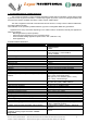
70-M USER’S MANUAL R70MP10: Receiver with PWM outputs (10 outputs) Available frequencies (ISM bands) Power supply Number of outputs Protection Antenna Working channel selection Weight Dimensions EEPROM Status signalling Connexions Maximum current per output Maximum current output (total) PWM outputs frequency range Output accuracy Electrical input protection Electrical output protections Operating temperature Storage temperature (24h) Storage temperature –long periodsDisconnecting security R70MR11: Receiv
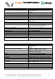
70-M USER’S MANUAL R70MR06: Receiver with output relays (6 outputs) Available frequencies (ISM bands) Power supply (depending on the model) Number of outputs Protection Antenna Working channel selection Weight Dimensions EEPROM Status signalling Connexions Maximum current over resistive load Operating temperature range Storage temperature (24h) Storage temperature –long periodsComsumption (maximum) 70-M V1.1 (05/07) 120009-0D.pdf 70-M V1.1 (05/07) 120009-0D.
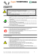
0-M USER’S MANUAL 2.- SAFETY INSTRUCTIONS 2.1.- GENERALS These instructions must be read carefully. This will allow you to install, use and maintain this device in a proper state, reducing the risk of incorrect use. Do not install the equipment in machines for the elevation of people or in explosive atmospheres.
70-M USER’S MANUAL 2.3.- FCC RECOMMENDATIONS (only valid for equipment that works in 915MHz ISM band) This device complies with Part 15 of the FCC Rules. Operation is subject to the following two conditions: 1. This device may not cause harmful interference, and 2. This device must accept any interference received, including interference that may cause undesired operation. Changes or modifications not expressly approved by the manufacturer could void the user's authority to operate the equipment.
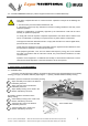
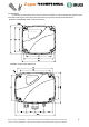
70-M USER’S MANUAL 3.2.-RECEIVER Find an easy access location for the receiver, free from obstacles, in order to facilitate the reception of the transmitter’s radio signal, and far away from elements that can produce intense electric disturbance. R70MP10 and R70MR06 models receiver dimensions: R70MR11 model receiver dimensions: 70-M V1.1 (05/07) 120009-0D.pdf 70-M V1.1 (05/07) 120009-0D.pdf IKUSI se reserva el derecho de modificar esta información sin previo aviso.
70-M USER’S MANUAL 3.3.- STARTING UP. TRANSMITTERS: Switching on T70MG10 transmitter model: T70MG10 1- Insert the batteries (two AA type batteries). 2- Press ON/OFF function, until the first green LED flashes. The LED will keep blinking in green colour while the transmitter is in the initializing process; later the LED lights off. The transmitter remains in “stand-by” mode.
70-M USER’S MANUAL RECEIVERS Proceed to connect the power supply and the output connections. Use the plug-in terminals and the connection block diagram provide in this manual (page 11). LED’s signalling in correct operating mode: 1) No radio link with the transmitter: “Power”: solid green. “Hard-OK”: solid green. “Signal”: Blinking if there are transmitters near and in the same band. 2) There is a radio link with the transmitter: “Power”: solid green. “Hard-OK”: solid green. “Signal”: green blinking fast.
70-M USER’S MANUAL 4.2.- MAINTENANCE / TROUBLE SHOOTING GUIDELINE (TRANSMITTERS WITHOUT DISPLAY) TRANSMITTER’S LED SIGNALLING MODELS: T70MG10/T70MH3/T70MH2 Lost Correct operating Activated mode function Status Low battery transmitter ERROR frame found Green flashing LED LATENCY Switches to SWITCHED OFF Without signal Red LED and buzzer Without signal mode SWITCHED ON: Red LED + buzzer continuously activated. Red LED + buzzer. Red LED and buzzer TRANSMISSION continuously activated.
70-M USER’S MANUAL 4.3.- MAINTENANCE / TROUBLE SHOOTING GUIDELINE (TRANSMITTER WITH DISPLAY) TRANSMITTER’ SIGNALLING MODEL: T70MH3D Correct operating Activated Status Lost transmitter Low battery mode function Without signal Without signal ERROR frame found ERROR LATENCY It switches to OFF state Buzzer Without signal continously activated SWITCHED ON: Buzzer sounds TRANSMISSION It switches off after 5 minutes ERROR MODE (max. 1 min.
70-M USER’S MANUAL 5.- RECEIVERS 5.1.- TYPES OF RECEIVERS (CONNECTIONS BLOCK DIAGRAMS) R70MP10: PWM OUTPUT RECEIVER (10 OUTPUTS). The voltage DC of the power supply (from 9v to 35v DC, is conducted to the common wiring of the ten output switches (OUT1 until OUT10), through a SAFETY switch which guarantees the output disconnection in case of breakdown of some of the outputs. The “RELAY” switches between two fixed positions NO (normally opened) and NC (normally closed).
70-M USER’S MANUAL 5.2.- MAINTENANCE / TROUBLE SHOOTING GUIDELINES RECEIVER’S LED SIGNALING LED POWER COLOUR GREEN HARDOK GREEN RED HARDOK STATUS Switch On if powered Solid green LED if no error detected DATA ID RELAY ORDER GREEN GREEN OK Solid red LED if one of these errors appears: Electronic board hardware - Watchdog activated / breakdown Oscillator breakdown / wrong ROM checksum - Reset activated Replace the electronic board Blinking fast : wrong EEPROM checksum / Data corrupted.
70-M USER’S MANUAL 6.- RADIO REMOTE SYSTEM FUNCTIONALITIES 6.1.- GENERALS The transmitter models without LCD display have restrictions with the access to the programation parameters, due to the impossibility to show the Software Menu in the Programming Mode. The remote system’s receiver remembers the last ID used by the last current working transmitter. This transmitter can be considered as the receiver’s owner.
70-M USER’S MANUAL 6.3.- BASE CHANNEL CHANGE (TRANSMITTER MODELS:T70MG10;T70MH3D;T70MH3;T70MH2) T70MG10 TRANSMITTER MODEL 1) With the transmitter switched off, press “ON/OFF”. Transmitter in stand-by or LOW CONSUMPTION mode. 2) Entering the base channel changing mode: BASE CHANNEL CHANGE MODE (Press “5” and “10” functions simultaneously) -> Wait until the orange LED lights on continuously.
70-M USER’S MANUAL T70MH3D TRANSMITTER MODEL 1) With the transmitter switched off, press “ON/OFF”. Transmitter in stand-by or LOW CONSUMPTION mode. 2) Entering in the base channel changing mode: + BASE CHANNEL CHANGE MODE (Press “RIGHT” and “START” functions simultaneously) -> Message in the LCD display: “FREQ CHANGE” 3) The current base channel information is displayed: “Freq Change” “Channel NN” -> (01,02,03……….
70-M USER’S MANUAL 6.4 ID RELEASE (LIB ID) (TRANSMITTER MODELS:T70MG10;T70MH3D;T70MH3;T70MH2) T70MG10 TRANSMITTER MODEL A) ID release from the current transmitter which has the ownership of the receiver. 1) With the transmitter switched off, press “ON/OFF”. Transmitter in stand-by or LOW CONSUMPTION mode. 2) To enter in LIB ID mode, press simultaneously “4” and “10” functions, until the orange LED lights on. 3) To execute ID release, press “10” function.
70-M USER’S MANUAL 6.5 AUTO TEACHING MODE (AUTO ID) (TRANSMITTER MODELS:T70MG10;T70MH3D;T70MH3;T70MH2) T70MG10 TRANSMITTER MODEL It allows to register a new transmitter into the receiver’s database -new ID- (maximum = 32 ID) 1) With the transmitter switched off, press “ON/OFF”. Transmitter in stand-by or LOW CONSUMPTION mode. 2) To enter in LIB ID mode, press simultaneously “UP” and “START” functions, until the orange + LED lights on.
70-M USER’S MANUAL 6.6 LOST TRANSMITTER SEARCHING MODE (TRANSMITTER MODELS: T70MG10;T70MH3;T70MH2) T70MG10 TRANSMITTER MODEL It allows to find one or more lost transmitters in the same working area. 1) With the transmitter switched off, press “ON/OFF”. Transmitter is stand-by or LOW CONSUMPTION mode. 2) To enter in SEARCH mode, press simultaneously “7” and “10” functions. Keep pressed until the orange LED lights continuously. + 3) Enter “3”-“1”-“3” function’s sequence. The SEARCH function will execute.
70-M USER’S MANUAL 6.7 PROGRAMMING PARAMETERS (PARAM) (TRANSMITTER MODELS: T70MG10;T70MH3;T70MH2 ) 1) When executing DOWNLOAD/UPLOAD LOCAL, if the EEPROM is wrong or not connected, the red LED will indicate “EEPROM Error” (red LED blinking during 5 secs. aprox.) and the transmitter switches to PARAM mode, ready to select a new sequence (DOWNLOAD LOCAL or UPLOAD LOCAL or DOWNLOAD REM). 2) In case of “Grave Error”, the red LED and the buzzer becomes active continuously.
70-M USER’S MANUAL T70MH3 TRANSMITTER MODEL 1) With the transmitter switched off, press “ON/STOP”. Transmitter in stand-by or LOW CONSUMPTION mode. 2) To enter in PARAM mode, press simultaneously “ENTER” and “START” functions. Keep pressed until the orange LED lights continuously. + 3) Entering modes: ► ► DOWNLOAD LOCAL ► ► ► UPLOAD LOCAL ► ► ► ► ► ► STAND-BY or LOW CONSUMPTION MODE DOWNLOAD REM T70MH2 TRANSMITTER MODEL 1) With the transmitter switched off, press “ON/STOP”.
70-M USER’S MANUAL 6.8 PROGRAMATION (TRANSMITTER MODEL T70MH3D) The availability to enter in programming mode is restricted to transmitter’s models with LCD (model T70MH3D -> Remote Programmer). The software architecture presents this following message’s levels: 1 M E S 1 M S . E A G X1 S 1 M . E E S A X1 S 1 M . S . E G E X2 A G X1 S . S E X2 A . G X3 E TRANSMITTER’S SWITCH ON PROCESS With the transmitter switched off, press “ON/STOP” during 2 secs.
70-M USER’S MANUAL 6.8.1- PROGRAMMING MODE: BLOCK DIAGRAM PROGRAMATION 1 PARAMETERS 1.0 DOWNLOAD LOC EP70 -> Internal Tx EEPROM 1.1 UPLOAD LOC 1.2 DOWNLOAD REM Internal Tx EEPROM -> EP70 70-M V1.1 (05/07) 120009-0D.pdf 70-M V1.1 (05/07) 120009-0D.pdf Internal Rx EEPROM -> Internal Tx EEPROM (+ EP70 if connected) IKUSI se reserva el derecho de modificar esta información sin previo aviso. IKUSI reserves the right to modify this information without prior notification.
70-M USER’S MANUAL 2.0 ADJUST 2.0.1 SEARCH MODE 2.0.2 TOUT LATENCY 2.0.3 TOUT OFF 2.0.4 T STOP SEARCH MODE ON / OFF TOUT LATENCY MIN N TOUT OFF MIN NN T STOP SEG NN .N 2.0.5 TELEALIGN SELECT OUT 1….10 SELECT OUT START (*) (*) The START relay activation can be programmed as MOMENTARY or LATCHING, as well, while pressing START function. 2.0.5.START OUT MODE (*) OUT MODE LATCH / TEMP 70-M V1.1 (05/07) 120009-0D.pdf 70-M V1.1 (05/07) 120009-0D.
70-M USER’S MANUAL 6.8.2.- PROGRAMMABLE PARAMETERS (TELE-ALIGNED): Parameter START (KEY SOFTWARE) SEARCH MODE TOUT LATENCY TOUT OFF TSTOP OUTMODE SOFTSTART SOFTSTOP ACCELRAMP DECELRAMP PWM FREQ 70-M V1.1 (05/07) 120009-0D.pdf 70-M V1.1 (05/07) 120009-0D.pdf PROGRAMMABLE VALUES (TELE-ALIGNED) Default value Range (programmable values) T70MG10: NO T70MH3/T70MH3D/T70MH2: ◄ ► See User’s Manual OFF ON, OFF. (SEARCH MODE) 4min 1 to 6min; steps of 1 min, and infinite (“INF” value) minutes.
70-M USER’S MANUAL 6.8.3.- OUTPUT PROGRAMMING MODES (TELE-ALIGNED) In Menu 2.0.5.x.0 OUTMODE: select “MOMENTARY” for MOMENTARY OUTPUT and “LATCHING” FOR LATCHED (LOCKED) OUTPUT. OUTPUT PROGRAMMING WITH ONE STEP KEYPAD: “MOMENTARY” OUTPUT MODE or “LATCHING” OUTPUT MODE. 1) RAMP-UP PROGRAMMING (RAMP= ON) 2) ON/OFF PROGRAMMING (RAMP= OFF) V MAX = 100% V MAX = 100% In 2.0.5.x.
70-M USER’S MANUAL ▼ ▲ In 2.0.5.x.3.1 software menu DECEL RAMP, select: DECEL TIME SEG NN T=0 Tmax = 5s Tmin = 0s T=0 In 2.0.5.x.3.0 software menu ACCEL RAMP, select: ACCEL TIME SEG NN Tmax = 5s Tmin = 0s V MAX = 100% The ramp up time (up or down) is fully programmable (Tele-Aligned). The programmed time is the time to achieve Vmax. from 0v in each PWM output signal. TWO STEP KEYPAD PROGRAMMING 1) RAMP-UP PROGRAMMING (RAMP= ON) 2 VEL/SPEED = ON V OUT = V max = 100% In 2.0.5.x.
HEADQUARTER - SPAIN IKUSI - Ángel Iglesias S.A. Pº Miramón, 170 20009 San Sebastián SPAIN Tel.: +34 943 44 88 00 Fax: +34 943 44 88 20 ikusi@ikusi.com www.ikusi.com AUSTRALIA - NEW ZEALAND IKUSI ANZ PTY LTD Tel.: +61 3 9720 7022 Fax: +61 3 9720 7422 ika@ikusi.com CHILE INGENIERÍA IKUSI CHILE, LTDA. Tel.: +56 2 335 9661 Fax: +56 2 233 7511 ikc@ikusi.com FRANCE IKUSI FRANCE SARL Tel.: +33 1 43 03 52 22 Fax: +33 1 43 03 52 42 ikf@ikusi.com MEXICO IKUSI-GS MÉXICO, S.A. DE C.V. Tel.
70-M V1.1 (05/07) 120009-0D.pdf 70-M V1.1 (05/07) 120009-0D.pdf IKUSI se reserva el derecho de modificar esta información sin previo aviso. IKUSI reserves the right to modify this information without prior notification.
70-M V1.1 (05/07) 120009-0D.pdf 70-M V1.1 (05/07) 120009-0D.pdf IKUSI se reserva el derecho de modificar esta información sin previo aviso. IKUSI reserves the right to modify this information without prior notification.
70-M V1.1 (05/07) 120009-0D.pdf 70-M V1.1 (05/07) 120009-0D.pdf IKUSI se reserva el derecho de modificar esta información sin previo aviso. IKUSI reserves the right to modify this information without prior notification.
70-M V1.1 (05/07) 120009-0D.pdf 70-M V1.1 (05/07) 120009-0D.pdf IKUSI se reserva el derecho de modificar esta información sin previo aviso. IKUSI reserves the right to modify this information without prior notification.