DC Ceiling Fan with Remote Control Models: ILG8CF52B / ILG8CF52W ILG8CF56B / ILG8CF56W OWNER'S MANUAL PLEASE READ AND SAVE THESE INSTRUCTIONS 1
IMPORTANT SAFETY INSTRUCTIONS Read instructions carefully before assembling or installing your fan. It is important that you observe all safety information to help prevent personal injury and/or property damage. 1. To ensure the success of the installation be sure to read the instructions and study the diagrams thoroughly. 2. For your safety, all electrical connection and disconnection must be performed by a Licensed Electrician, in accordance with the National Electrical Code, ANSI/NFPA 70. 3.
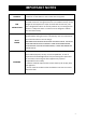
IMPORTANT NOTES FAN CONTROL Your warranty will be void if a solid-state dimmer fan controller controller is used. ONLY use the remote control supplied. FAN INSTALLATION Under our warranty terms, this ceiling fan must be installed by a licensed electrician. Ceiling fans that are not installed correctly can be dangerous and expensive to repair and will void the warranty.
BEFORE INSTALLATION Unpack your ceiling fan carefully. Remove all parts and hardware. Place fan motor on a cloth or soft surface to avoid damage to the finish. Do not lay motor housing on its side –the decorative housing may become bent or damaged. Verify that all parts are present before starting assembly. Check the packaging carefully for missing parts. Examine all parts.
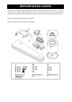
CONTENTS REF 1 2 QTY 1 1 DESCRIPTION 3 3 Blades 4 5 3 3 Blade holder Blade holder kit 6 7 1 1 Bottom cover Remote transmitter with holder 8 1 Remote receiver 9 1 3/16x35mm Wooden Screw x3 1/4 Flat Washer x3 Wire Caps x 3 10 1 1/16x8mm Blade Assemble Screw x 10 11 1 1/4x7mm Hanging Bracket Set Screw x 7 Mounting Bracket Fan assembly with hanger cover, down rod canopy cover and canopy TOOLS REQUIRED (Not Included): - Phillips / Flat head screw driver - Pair of pliers - Adjustable Span
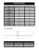
SPECIFICATION Model# ILG8CF52B/ ILG8CF52W ILG8CF56B/ ILG8CF56W Size 52” 56” Voltage(V) 120 120 Frequency (Hz) 60 60 Wattage(W) 35 35 AMPS(A) 0.5 0.5 RPM 155 135 CFM 5600 6200 Blades 3 3 Blade Angle 14 14 Speeds 6 6 Net Weight (KG) 4.7 4.71 Certification UL, cUL UL, cUL Dimensions(mm) Model# D H ILG8CF52B ILG8CF52W ILG8CF56B ILG8CF56W 1320.8 1320.8 1422.4 1422.4 344.37 344.37 344.37 344.
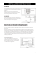
INSTALLATION INSTRUCTIONS WARNING To avoid possible electrical shock, be sure electricity is turned off at the main fuse box before installation. (Figure 1) NOTE: If you are not sure if the outlet box is grounded, contact a licensed electrician for advice, as it must be grounded for safe operation. WARNING The fan must be hung with at least 7 feet above the floor, and 11-1/8in spacing from the tip of the blade to the nearest objects or walls.
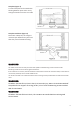
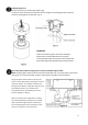
Deep box (Figure 4) A 2-1⁄4in.deep box can be attached to blocking between joists and is roomy enough to handle more than one cable. Deep box with brace (Figure 6) Paired with a deep box, this hanger is meant to Span between two joists and takes the place of wooden blocking. WARNING The outlet box must be securely anchored and capable of withstanding a load of at least 35 lbs. Mounting bracket must seat firmly against outlet box. If the outlet box is recessed, remove wallboard until bracket contacts box.
Install Mounting bracket Secure the mounting bracket to the outlet box Marked "Acceptable for Fan Support of 15.9 kg (35 lbs.) or less" and use mounting screws provided with the outlet box. Securely attach the mounting bracket to ceiling outlet box acceptable for ceiling fan support. (Figure 6) This fan hanging system supports a maximum 20degree angled ceiling installation.
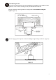
Installing Down rod. Lift fan assembly onto mounting bracket. Fig.8 Ensure the notch of ball joint is positioned on the stopper of mounting bracket to prevent Fan from rotating when in operation. Fig. 9 WARNING Failure to seat tab in groove could cause damage to electrical wires and possible shock or fire hazard. To avoid possible shock, do not pinch wires between the down rod/hanger ball assembly and the hanger bracket. Secure the safety cable to ceiling joist or structure member support cable.
Connect wires to supply/grounding wires using connectors as shown below. After making the wire connections, the wire should be spread apart with the grounded Conductor (neutral Wire) and the equipment-grounding conductor (Ground Wire) on one side of the outlet box and the ungrounded conductor (Live Wire) on the other side of the outlet box. The splices after being made should be turned upward and pushed carefully up into the outlet box. ※Use wire cap to connect the wires according to Figure 11.
Install Canopy Loosen 1 screw from the key hole of the mounting bracket bottom and remove 1 screw from the round hole of the mounting bracket bottom. Slide the canopy up to the mounting bracket and place the key hole on the canopy over the screw on the mounting bracket, turn canopy until it locks in place at the narrow section of the key hole, secure it by tightening the 1 set screw to the key hole. Secure the screw removed from the round hole into the round hole.
REMOTE CONTROL Figure 15 The control system has a last memory function. The system stores the current setting in memory upon power down and restore setting on next power up. The remote control and fan are pre-programmed. If, however they don’t function together when first installed, or you wish to control 2 fans using the same remote, or pair a replacement remote control to your existing fan, use the following procedure. Remote Pairing Instruction DO NOT PRESS ANY OTHER BUTTONS DURING THIS PROCESS 1.
BALANCING / WOBBLYING TROUBLE SHOOTING Please note that all ceiling fans are not the same, even in the same model—some may move more or less than others. Movement of a couple of centimeters is quite acceptable and does not suggest the fan will fall down. Even though all blades are weighted and grouped by weight, it is impossible to eliminate wobble altogether. This should not be considered a fault. Ceiling fans tend to move during operation due to the fact that they are not generally rigidly mounted.
MAINTAINANCE Periodic cleaning of your ceiling fan is the only maintenance required. Use a soft brush or lint free cloth to avoid scratching the paint finish. Please turn off electricity power when you do so. Do not use water when cleaning your ceiling fan. It could damage the motor or the wooden blades and create the possibility of an electrical shock. Motor has permanently lubricated ball bearing. No need to oil.
TROUBLE SHOOTING If you have difficulty operating your new ceiling fan, it may be the result of incorrect assembly, installation, or wiring. In some cases, these installation errors may be mistaken for defects. If you experience any problems, please check the following trouble shooting guide. If a solution to the problem cannot be found, please consult with a licensed electrician. Do not attempt any electrical repairs by yourself.
Warranty Information Register your product at our website: Or visit iLivingUSA.com/register-product Feedback Love it? Help us make the product more for you. Let us know with a customer review. Please visit: https://www.amazon.com/review/review-your-purchases# At iLivingUSA, we are committed to bringing top quality products to our customers. iLIVING USA 860 Mahler Rd Burlingame, CA 94010 Tel: 1-800-317-1688 Email: service@ilivingusa.com Like us on Facebook: https://www.facebook.