Walk-In Cooler & Freezer Installation/Maintenance & Owner’s Instructions For All W. A. Brown & Son, Inc. Models W.A. Brown & Son, Inc. 209 Long Meadow Drive • Salisbury, NC 28147 Phone: 704-636-5131 • Fax: 704-637-0919 Website: www.wabrown.
Table of Contents Page No. Cam Lock Installation ............................................................................3 Door Section Maintenance ............................................................17-19 Drop Off (factory assembled) Walk-Ins ................................................11 Duro-Last Roof Cap Installation ............................................................8 EZ Pack Refrigeration Installation ......................................................
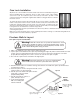
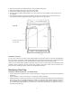
Receiving and Uncrating Congratulations! You have purchased a brand new W.A. Brown & Son, Inc. Walk-In Cooler or Freezer. To ensure proper set-up and many years of trouble free use, read and follow these instructions carefully before and during installation. This manual covers the basic installation of a standard walk-in. See sheets enclosed with shipment for installation instructions for items not covered in this manual.
Floor Preparation and Installation Installation instructions are provided for walk-ins with insulated floor panels or walk-ins set on spline. Instructions are also provided for the application of walk-ins in areas requiring adherence to wind or seismic loads. Warning! A level walk-in is essential. If the floor is not level, the vertical panels will not be plumb and the hinged door will not operate properly and panels will not seal properly.
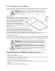
Cam Lock Installation All panels are connected with a mechanical Cam lock which is activated by using a hex wrench (included with your shipment). There are both a male section, and a female section. The locks are foamed in place and securely anchored to provide a solid connection, when the locking arm is tightened around the locking pin which is located in the female section. To operate the latch, insert the wrench through the access hole which is located on the inside of each panel.
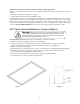
Installation of floor panels secured for seismic and wind - exterior applications After the floor is installed per the instructions above, obtain the hardware and tools for the application of “Tapcon” anchors. 1. 1/4" “Tapcon” Phillips flat head anchors or equal 2. “Tapcon” drill bit; 3/16" x 6 1/2" (No. 790-1036 or equal) Drill through the female cam lock located in the floor panel into the concrete pad to a depth of 2" or more to insure the anchor does not bottom out.
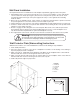
Wall Panel Installation See separate instructions for installation if box has multiple compartments (page 6-7) with a “Tee” panel. 1. Start installation at the corner panel nearest the door or, if cooler is to be installed in a corner, start with the corner located on the inside. (See Figure 7) Place the first corner panel into position. Be sure the ‘arrow’ is pointed up and the male tongue of the panel (edge w/cam locks) is on the right side when standing inside the walk-in. 2.
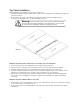
Top Panel Installation Standard Walk-In: Begin installation of top panels at either end. 1. Check the drawing sent with the walk-in and assemble the top as indicated on this drawing. See Figure #8 for typical top layout. 2. Do not lock the top panels to the wall panels until all panels are positioned and aligned. If top is too large to shift (on larger boxes), go ahead and align, then lock.
3. 4. 5. 6. After the floor panels are installed and level, erect the partition wall panels. After this the partition wall can be set in place and locked. Position the remaining wall panels and lock them all down. The top panels should be installed with the “Tee” Section first, then work toward the ends until all the tops are installed. 7. The combination walk-in must be level and square. Use the same methods as mentioned earlier in this manual.
• • • • Repeat this procedure on all four sides. Trim extra material prior to sealing. Cut, fold, and glue roof membrane using contact cement (not provided) Position flashing to corner and form to fit by applying hand pressure to outside edges. Secure the corner flashing to the sidewalls. Install to existing wall • Allow membrane to extend up the existing wall approximately 6". • Position 2 1/2" cove and fasten. Apply contact cement or caulk (not provided by W. A.
Fiber Cement Finish Panels Installation Fiber Cement panels are available in vertical siding and smooth styles. Smooth Fiber Cement is designed to have a Stucco finish applied in the field or to be painted. Vertical siding style is meant to be field painted to more closely match existing construction. See instructions below on painting Fiber Cement. Inspect all panels as outlined on page 1. All door sections and Buck Openings on Fiber Cement Walk-Ins are constructed using W.A.
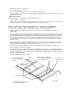
Top Panel Installation Indoor walk-ins with dimensions of more than 15' 5" in both length and width (Figure #11) must have some type support for ceiling panels. Exterior beams, interior beams or column supports can be used. In these cases, it is imperative to properly install the rod assembly provided to properly support the ceiling panels and keep them from sagging. Failure to do so may result in an unsatisfactory installation.
Top Panel Trim Installation Installation of 1/2" x 5" Trim on Top Panels • Trim is used to finish off all Walk-In Cooler and Freezers other than Drop-Off units and is left to the installer, as not all field conditions are identical. Trim is packed with each shipment (as required) from W. A. Brown. • Install corner trim pieces first. Use four #6 self tapping screws supplied (See Figure 13-1). Install trim metal between corners. Overlap all joints by 1/2". Use one screw every 2' (See Figure 13-2).
EZ Pack Installation Instructions (See Installation Guide taped to top of each unit.) Installing the Refrigeration System A qualified technician should install the refrigeration. Contact the dealer from who you purchased your Walk-In for a qualified technician. Carefully raise refrigeration system to top of walk-in. Insert projecting sleeve of evaporator box in to cut out of panel. Install louvered grill on interior side of top panel. Grill should be installed with fan motors.
Roof Cap & Curb Installation (Figure #14) 1. Make sure Walk-in top is completely clean of any debris. 2. Run bead of Silicone around cut-out opening. 3. Install 2 piece Wood Curb (provided) onto Walkin top with counter sink screws (provided). 4. Follow procedures for installing Membrane Roof Cap over Wood curb, page 7. 5. Cut rubber roof cap over opening in X shape. 6. Roll rubber roof cap inside opening. 7. Run bead of Silicone around cut-out opening. 8. Set refrigeration unit in place. 9.
Housekeeping and Safety Housekeeping and Safety Recommendations Please use caution when inside any walk-in. The floor may become slippery if allowed to become wet or greasy. To provide user safety, to maintain optimum performance and long life of this product, we recommend regularly reviewing the following procedures with anyone that may enter the walk-in: • Keep all walkway surfaces clean and free of spilled liquids and food particles. All aisles must be kept clear for passage.
How To Call for Service Repair After your W. A. Brown & Son, Inc. Walk-in has been correctly installed, and the refrigeration system properly connected your new Walk-in should provide you years of uninterrupted service. Should your Walk-In ever require service, please have the following information available upon initiating a service call. Determine the date your walk-in was placed into service and enter it here.
LIFETIME LIMITED CABINET WARRANTY W. A Brown & Son, Inc. warrants to the original purchaser, the full foamed-in-place aluminum and stainless steel panels manufactured and sold by it, to be free from defects in material and workmanship under normal use and service for life from the date of original installation by an authorized representative. All other panels manufactured by W. A. Brown & Son, Inc.
Instructions for removing Door Leaf with Spring Loaded Hinges (See Figure #15) 1248 Spring Hinge 1. Open Door to dwell position, stopping at approx. 120˚. 2. Put mark on floor to indicate position of Door. See sketch. 3. Lift Door off frame. 4. To replace Door, line up Door with mark on the floor. 5. Place Hex Hole in hinge straps over Hex Rods and lower Door. Figure #15 120˚ Strap Door Mark Instructions for Door Hinge Pin replacement, (See Figure #16) 45˚ Approx. 10˚ Approx.
Description Of Numbered Door Section Components 1. Vapor Proof Light (use standard light bulb, maximum 100 watts) with plastic coated glass 2. Electrical Junction Box 3. Door Closer 4. Temperature Indicating Device (Dial Shown) 5. Light Switch With Neon Pilot Light 6. Door Latch Assembly 7. Heater Cable 8. Door Hinge 9. Threshold Plate 10. Drag Gasket 11. Floor Panel All wiring contained within the door section is 115/60/1 with the exception of the digital thermometer when used.
Guidelines For Replacing Door Heater Cable If door jamb is sweating or icing, you need to use the following guidelines. 1. 2. 3. 4. 5. 6. 7. 8. 9. 10. 11. 12. Check the circuit breaker to see if it is in the on position and functioning properly. Check the heater cable (#1) for current at the junction box. Turn the circuit breaker off that supplies electricity to the heater cable Check the heater cable for continuity. If the circuit is open you will need to replace the heater cable.
Relacing Door Gasket 1. Open the door to a 90˚ angle. Using two people, lift the door leaf from the hinges and place it horizontally across two saw bucks or similar supports. (CAUTION: When removing door leaf from door section use caution not to dislodge the hinge pins.) See page 17 if this occurs. 2. Start at the bottom of the door removing the old gasket. Remove it by pulling it from the groove. 3. Lay the new gasket on the door leaf. Begin by pushing the corners in place. 4.
Replacing Flush Dial Thermometer Dial Thermometer: Complete Field Replacement - Flush Mount in Figure #22 Locate thermometer to be replaced. From inside of box, cut wire tie holding bulb. Remove screws from flange face with screw driver. Work flange free from section. A putty knife works well for this purpose. Applying uniform pressure, pull bulb through section. Clean residual silicone from section. Retrieve new thermometer, and unwrap.
Replacing The Digital Thermometer Turn off breaker before disconnecting wires. If the thermometer does not register correctly you will need to check the following: 1. 2. 3. 4. Check the voltage on the load side of the transformer. It should be 12 volts. If the voltage is not 12 volts on the load side of the transformer, check the line side to confirm that proper voltage is reaching the transformer. If you have 115 volts on the line side and nothing on the load side you will need to change the transformer.
Electrical Hook-Up to Junction Box 1. Connect incoming conduit to 3/4 diameter hole on right side of junction box. 2. Selection of conduit type, connection method and wire type in accordance with local codes. Responsibility of installing contractor. Once 120 volt power is pulled to the junction box, insert a sharp pointed tool into the box marked 1 . Apply pressure downward to open the wire termination opening in the box marked "Black". Insert Black wire and release tool.
Figure #30 24
Refrigeration Trouble Shooting Guide Always use a certified trained Refrigeration Technician when repair of your refrigeration system is required.
Operating Instructions for TAI-2000D-12 Temperature Display & Alarm Input Voltage 12 VAC Only DO NOT CONNECT THIS UNIT TO 120VAC The line voltage of 120VAC shall be connected to the two (2) black leads, one with a white sleeve, from the transformer provided and attached to the exterior of the junction box located on the interior of the cooler above the door. These wires will be found within the junction box. Connect one black to the hot leg & one black with white sleeve to the neutral leg.