
Owner's Manual
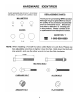
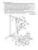
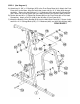

STEP 4 (See Diagram 4)
A.) Attach two ∅1 5/8” x ¼” Bushings (#76) to the holes on the Upper Frame (#3). Attach the
Front Press Base (#14) to the Bushings. Align the holes then insert a 7” Axle (#33) through
the holes. Secure the Axle with two M6 x ¼” Slotted Set Screws (#92).
B.) Insert a M10 x 6 ¾” Allen Bolt (#84) through the upper holes on the Front Press Base (#14).
Securely tighten it with two ∅ ¾” Washers (#94) and one M10 Aircraft Nut (#96).
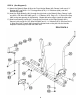
C.) Attach two Front Support Frames (#11) to the Main Base Frame (#1). Secure it with one M10
x 2 ¾” Carriage Bolt (#79), ∅ ¾” Washer (#94), and M10 Aircraft Nut (#96).
D.) Attach the Frames to the Seat Support (#10). Secure them with one M10 x 2 ¾” Carriage
Bolt (#79), ∅ ¾” Washer (#94), and M10 Aircraft Nut (#96).
E.) Attach two ∅1” Bushings (#70) to the Leg Developer (#12). Place the Leg Developer in
between the two Support Frames. Align the holes and secure it with one M12 x 3” Allen Bolt
(#81), two ∅1” Washers (#95), and one M12 Aircraft Nut (#97).
DIAGRAM 4
7