NOTE: Please read all instructions carefully before using this product Table of Contents Safety Notice MARCY HOME GYM Hardware Identifier Assembly Instruction APEX Parts List Resistance Chart Warranty Ordering Parts Model APEX Retain This Manual for Reference 06-24-02 OWNER'S MANUAL IMPEX FITNESS PRODUCTS 14777 DON JULIAN RD., CITY OF INDUSTRY, CA 91746 Tel: (800) 999-8899 Fax: (626) 961-9966 www.impex-fitness.com info@impex-fitness.
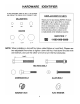
TABLE OF CONTENTS BEFORE YOU BEGIN....................................................................................……….. 1 IMPORTANT SAFETY NOTICES...................................................................……….. 2 HARDWARE IDENTIFIER.....….....................................................................……….. 3 ASSEMBLY INSTRUCTIONS.........................................................................……….. 4 PARTS LIST…………………………………………………………………………………...14 WARRANTY............................
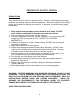
IMPORTANT SAFETY NOTICE PRECAUTIONS This exercise machine is built for optimum safety. However, certain precautions apply whenever you operate a piece of exercise equipment. Be sure to read the entire manual before you assemble or operate your machine. In particular, note the following safety precautions: 1. Keep children and pets away from the machine at all times. DO NOT leave children unattended in the same room with the machine. 2. Only one person at a time should use the machine. 3.
3
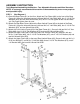
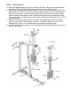
ASSEMBLY INSTRUCTION Tools Required Assembling the Machine: Two Adjustable Wrenches and Allen Wrenches. NOTE: It is strongly recommended this machine to be assembled by two or more people to avoid possible injury. STEP 1 (See Diagram 1) A.) Place the Base Frame (#1) on the floor. Attach two Foot Plates (#30) to the front of the Base Frame (#1). Align the holes and secure it with two M10 x 3” Hex Bolts (#66), four ∅ 13/16” Flat Washers (#75), and two M10 Aircraft Nuts (#78).
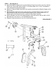
STEP 2 (See Diagram 2) A.) Place two Rubber Bumpers (#37) onto the Base Frame (#1). Align the two holes and push two Weight Plate Guide Rods (#23) through the Bumpers into the Base Frame. B.) Slide fourteen Selective Weight Plates (#84) from top of the Guide Rods (#23) down to the Base Frame (#1). NOTE: The grove on the Plates should always face down and toward the left side of the machine. Insert the Selecting Rod (#22) into the center hole on the Plates.
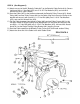
STEP 3 (See Diagram 3) A.) Attach the Butterfly Support (#13) and the Butterfly Pulley Frame (#15) to the Front Vertical Frame (#3). Secure them with two M10 x 3” Hex Bolts (#66), four ∅ 13/16” Flat Washers (#75), and two M10 Aircraft Nuts (#78). B.) Attach a 2” Square Rubber Cap (#53) to the opening underneath the Butterfly Support (#13). See A View. C.) Place a Butterfly Cable Guide (#14) onto the axle on the Right Butterfly (#12).
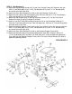
STEP 4 (See Diagram 4) A.) Attach the Leg Developer Holder (#17) to the Front Vertical Frame (#3). Secure it with two M10 x 3” Hex Bolts (#66), four ∅ 13/16” Flat Washers (#75), one 2” x 4 ¾” Bracket (#29), and two M10 Aircraft Nuts (#78). B.) Attach the Short Quick Release Pin (#34) to the Leg Developer Holder (#17). C.) Attach the Seat (#39) to the Seat Support (#18). Secure it with two ∅ 11/16” Flat Washers (#76), and two M8 x 2 9/16” Allen Bolts (#71). D.
STEP 5 (See Diagram 5) A.) Insert a ∅ 5/8” x 9 3/8” Axle (#31) halfway through the hole on the Base Frame (#1). B.) Attach the Front Press Left Base (#9) and the Front Press Right Base (#10) onto the Axle (#31) from both sides. Secure the Axle with two ∅ 13/16” Flat Washers (#75), M10 Aircraft Nuts (#78), and M10 Cone Shape Caps (#51). C.) Attach the Front Press (#8) to the Front Press Base (#9 & #10).
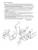
STEP 6 (See Diagram 6) A.) Attach one end of the 82” Butterfly Cable (#47) to the Butterfly Cable Guide (#14). Secure it with one M10 x 1” Hex Bolt (#70), two ∅ 13/16” Flat Washers (#75), and one M10 Aircraft Nut (#78). (See A Detail) B.) Draw the Cable (#47) to the bracket underneath the Butterfly Pulley Frame (#15). Attach Pulley (#60) and two Pulley Covers (#61) to the Cable.
STEP 7 (See Diagram 7) A.) Attach the 121” Cable (#50) to the top of the Upper Frame (#2). Attach a Pulley (#60) and two Pulley Covers (#61) to the beginning of the Cable. Secure it to the front open slot on the Upper Frame with one M10 x 2 3/8” Hex Bolt (#68), two ∅ 13/16” Flat Washers (#75), and one M10 Aircraft Nut (#78). B.) Draw the Cable towards back of the machine to the open bracket on the Upper Frame. Install a Pulley with two Pulley Covers.
STEP 8 (See Diagram 8 & Cable Loop Diagram) A.) Attach the 150” Cable (#48) to the Leg Developer (#16). Attach a Pulley (#60) and two Pulley Covers (#61) to the Cable. Secure it with one M10 x 2 3/8” Hex Bolt (#68), two ∅ 13/16” Flat Washers (#75), and one M10 Aircraft Nut (#78). B.) Draw the Cable to the first open bracket on the Base Frame. Install a Pulley set. C.) Draw the Cable underneath the Pulley and through the hole on the bottom of the Front Vertical Frame (#3). D.
STEP 9 (See Diagram 9 & Cable Loop Diagram) A.) Insert the 113” Cable (#49) through the upper hole on Front Vertical Frame (#3). Attach a Pulley (#60) to the Cable. (NOTE: There is no Cable Cover needed.) Secure it with one M10 x 2 9/16” Hex Bolt (#67), two ∅ 13/16” Flat Washers (#75), two Bushings (#62), and one M10 Aircraft Nut (#78). B.) Pull the Cable downwards to the open bracket on the Front Vertical Frame (#3) and install another Pulley set. C.
STEP 10 (See Diagram 10 & Cable Loop Diagram) A.) Attach two Weight Plate Covers (#26) to the Weight stack. Secure it with four M10 x 1” Hex Bolts (#70) and four ∅ 13/16” Flat Washers (#75). B.) Securely tighten all nuts and bolts previously installed from Step1 through 10.
PARTS LIST KEY NO.
IMPEX INC. LIMITED WARRANTY IMPEX Inc. ("IMPEX") warrants this product to be free from defects in workmanship and material, under normal use and service conditions, for a period of two years on the Frame from the date of purchase. This warranty extends only to the original purchaser. IMPEX's obligation under this Warranty is limited to replacing or repairing, at IMPEX's option. All returns must be pre-authorized by IMPEX.