
Owner's Manual
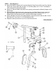


STEP 8 (See Diagram 8 & Cable Loop Diagram)
A.) Attach the 150” Cable (#48) to the Leg Developer (#16). Attach a Pulley (#60)
and two Pulley Covers (#61) to the Cable. Secure it with one M10 x 2 3/8” Hex
Bolt (#68), two ∅ 13/16” Flat Washers (#75), and one M10 Aircraft Nut (#78).
B.) Draw the Cable to the first open bracket on the Base Frame. Install a Pulley set.
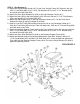
C.) Draw the Cable underneath the Pulley and through the hole on the bottom of the
Front Vertical Frame (#3).
D.) Draw the Cable through the first bracket behind the Front Vertical Frame. Install
another Pulley set on the second bracket.
E.) Pull the Cable upward towards the Double Floating Pulley Bracket (#27). Install
another Pulley set. Draw the Cable over the Pulley set then downward.
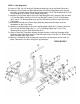
F.) Attach another Pulley set and Single Pulley Bracket (#21). Secure it with one
M10 x 1 ¾” Hex Bolt (#69), two ∅ 13/16” Flat Washers (#75), and one M10
Aircraft Nut (#78). Let the Bracket hanging for now.
G.) Pull the Cable upward and screw it at least ½” into the Single Floating Pulley
Bracket (#21) that was installed in Step 6C. NOTE: Do not screw the bolt all the
way into the Bracket. It may cause the Cable to be too short. After completing
the installation, check the tightness of the cable loop then come back to adjust
the bolt. Make sure to securely tighten the nut on the bolt.
11