
Owner's Manual


ASSEMBLY INSTRUCTION
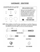
Tools Required Assembling the Machine: Two Adjustable Wrenches and Allen Wrenches.
NOTE: It is strongly recommended this machine to be assembled by two or more people to
avoid possible injury.
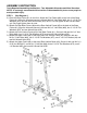
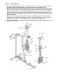
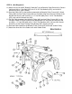
STEP 1 (See Diagram 1)
A.) Place the Base Frame (#1) on the floor. Attach two Foot Plates (#30) to the front of the Base
Frame (#1). Align the holes and secure it with two M10 x 3” Hex Bolts (#66), four ∅ 13/16” Flat
Washers (#75), and two M10 Aircraft Nuts (#78). NOTE: DO not tighten all the nuts and bolts
yet. Only finger-tighten them for now.
B.) Attach the Rear Base Frame (#6) and the Rear Vertical Frame (#5) to the back of the Base
Frame (#1). Align the holes and secure it with two M10 x 3” Hex Bolts (#66), four ∅ 13/16” Flat
Washers (#75), and two Aircraft Nuts (#78).
C.) Attach the Front Vertical Frame (#3) to the Base Frame (#1). Secure it with two M10 x 3” Hex
Bolts (#66), four ∅ 13/16” Flat Washers (#75), and two M10 Aircraft Nuts (#78).
D.) Attach the Upper Frame (#2) to the top of the Front Vertical Frame (#3). Secure it with two
M10 x 3” Hex Bolts (#66), four ∅ 13/16” Flat Washers (#75), one 2” x 6 5/16” Bracket (#4) and
two M10 Aircraft Nuts (#78).
E.) Attach the Upper Frame (#2) to the top of Rear Vertical Beam (#5). Secure it with one M10 x 2
9/16” Hex Bolt (#67), one M10 x 3” Hex Bolt (#66), three ∅ 13/16” Flat Washers (#75), one 2”
x 4” Bracket (#28), and one M10 Aircraft Nut (#78).
4