
Owner's Manual

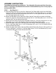
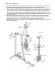
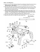

STEP 2 (See Diagram 2)
A.) Place two Rubber Bumpers (#37) onto the Base Frame (#1). Align the two holes and push
two Weight Plate Guide Rods (#23) through the Bumpers into the Base Frame.
B.) Slide fourteen Selective Weight Plates (#84) from top of the Guide Rods (#23) down to the
Base Frame (#1). NOTE: The grove on the Plates should always face down and toward the
left side of the machine. Insert the Selecting Rod (#22) into the center hole on the Plates.
Slide the Selector Stem (#46) and the Top Weight Plate (#83) onto the Guide Rods. Align
the hole and secure the Selector Stem (#46) to the Selecting Rod (#22) with a M10 x 1 9/16”
Socket Bolt (#82).
C.) Attach the Top Socket Assembly (#7) to the top of the Weight Plates Guide Rods (#23).
Secure it to the Upper Frame (#2) with two M10 x 3” Hex Bolts (#66), four ∅ 13/16” Flat
Washers (#75), one 2” x 4 ¾” Bracket (#29), and two M10 Aircraft Nuts (#78).
D.) Secure the Top Socket Assembly (#7) to the Weight Plates Guide Rods (#23) with two M6 x
5/8” Allen Bolts (#73).
5