NOTE: Please read all instructions carefully before using this product Table of Contents Safety Notice Hardware Identifier Assembly Instruction COMPETITOR WEIGHT BENCH CB-180 Parts List Warranty Ordering Parts Model CB-180 Retain This Manual for Reference 06-13-06 OWNER'S MANUAL IMPEX INC. 14777 DON JULIAN RD., CITY OF INDUSTRY, CA 91746 Tel: (800) 999-8899 Fax: (626) 961-9966 www.impex-fitness.com info@impex-fitness.
TABLE OF CONTENTS BEFORE YOU BEGIN...................................................................................…. IMPORTANT SAFETY NOTICES..................................................................…. HARDWARE IDENTIFIER.....…....................................................................…. ASSEMBLY INSTRUCTIONS........................................................................…. EXPLODED DIAGRAM……………………………………………………………… PARTS LIST........................................................
IMPORTANT SAFETY NOTICE PRECAUTIONS This exercise machine is built for optimum safety. However, certain precautions apply whenever you operate a piece of exercise equipment. Be sure to read the entire manual before you assemble or operate your machine. In particular, note the following safety precautions: 1. Keep children and pets away from the machine at all times. DO NOT leave children unattended in the same room with the machine. 2. Only one person at a time should use the machine. 3.
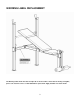
WARNING LABEL REPLACEMENT The Warning Label shown here has been placed on the Cross Brace. If the label is missing or illegible, please call customer service at 1-800-999-8899 for replacement. Apply the label in location shown.
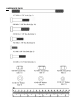
HARDWARE PACK 4
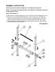
ASSEMBLY INSTRUCTION Tools Required Assembling the Machine: Two Adjustable Wrenches. NOTE: It is strongly recommended two or more people assembling this machine to avoid possible injury. STEP 1 (See Diagram 1) A.) Attach the Left & Right Upright Beams (#1 & 2) onto the Lower Upright Beams (#3). B.) Connect the Left & Right Upright Beams by a Cross Brace (#4) in the Mid-span.
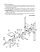
STEP 2 (See Diagram 2) A.) Insert the Main Support Frame (#5) into the Seat Support Frame (#6). Secure them with two M8 x 2 1/8” Hex Bolts (#18), two Brackets (#16), four Ø 5/8” Washers (#24), and two M8 Aircraft Nuts (#26). B.) Attach the Main Support Frame (#5) to the Cross Brace (#4). Secure it with two M8 X 2 1/8” Hex Bolts (#18), one Bracket (#16), four Ø 5/8” Washers (#24), and two M8 Aircraft Nuts (#26). C.) Attach the Seat Support Frame (#6) to the Leg Developer Holder (#7).
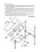
STEP 3 (See Diagram 3) A.) Insert the two Upper Backrest Supports (#8) into two Lower Backrest Supports (#9). Secure them with two M6 x 1 3/8” Hex Bolts (#20), four Ø ½” Washers (#25), and two M6 Aircraft Nuts (#28). B.) Attach the side-holes on the Lower Backrest Supports (#9) to each end of the pivot on the Seat Support Frame (#6). Align the holes and insert a M10 x 6 7/8” Axle (#17) through the holes. Secure it with two Ø ¾” Washers (#23) and M10 Aircraft Nuts (#27). Do not over tighten the Nuts.
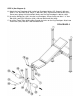
STEP 4 (See Diagram 4) A.) Attach the Leg Developer (#29) to the Leg Developer Holder (#7). Secure it with one M10 x 2 1/8” Hex Bolt (#19), two Ø ¾” Washers (#23), and one M10 Aircraft Nut (#27). Do not over tighten the Nut and Bolt. Make sure the Leg Developer is able to swivel. B.) Insert the Weight Post (#31) into the Leg Developer. Secure it with one M8 x 1 ¾” Hex Bolt (#22), two Ø 5/8” Washers (#24), and one M8 Aircraft Nut (#26). C.
9
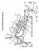
PARTS LIST KEY NO.
IMPEX INC. LIMITED WARRANTY IMPEX Inc. ("IMPEX") warrants this product to be free from defects in workmanship and material, under normal use and service conditions, for a period of two years on the Frame from the date of purchase. This warranty extends only to the original purchaser. IMPEX's obligation under this Warranty is limited to replacing or repairing, at IMPEX's option. All returns must be pre-authorized by IMPEX.