NOTE: Please read all instructions carefully before using this product Table of Contents Safety Notice Hardware Identifier MARCY CORNER GYM CR 5N Assembly Instruction Parts List Resistance Chart Warranty Ordering Parts Model MWM CR5N Retain This Manual for Reference 07-24-03 OWNER'S MANUAL IMPEX FITNESS PRODUCTS 14777 DON JULIAN RD., CITY OF INDUSTRY, CA 91746 Tel: (800) 999-8899 Fax: (626) 961-9966 www.impex-fitness.com info@impex-fitness.
TABLE OF CONTENTS BEFORE YOU BEGIN...................................................................................... 1 IMPORTANT SAFETY NOTICES..................................................................... 2 HARDWARE IDENTIFIER.....…....................................................................... 3 ASSEMBLY INSTRUCTIONS...............................................................…..........4 PARTS LIST…………………………………………………………….……….…….23 RESISTANCE CHART……………………………………………………………….
IMPORTANT SAFETY NOTICE PRECAUTIONS This exercise machine is built for optimum safety. However, certain precautions apply whenever you operate a piece of exercise equipment. Be sure to read the entire manual before you assemble or operate your machine. In particular, note the following safety precautions: 1. Keep children and pets away from the machine at all times. DO NOT leave children unattended in the same room with the machine. 2. Only one person at a time should use the machine. 3.
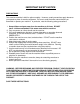
3
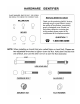
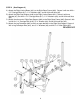
ASSEMBLY INSTRUCTION Tools Required Assembling the Machine: Two Adjustable Wrenches and Allen Wrenches NOTE: It is strongly recommended two or people assembling this machine to avoid possible injury. STEP 1 (See Diagram 1) A.) Place the Right Base Frame (#46) and Left Base Frame (#87) on the floor, at a right angle to each other. Attach the Rear Vertical Beam (#50) to the joint and align the holes. Secure the holes with two M10 x 3” Carriage Bolts (#64), ∅ 3/4” Washers (#6) and M10 Aircraft Nuts (#5).
STEP 2 (See Diagram 2) A.) Attach the Right Vertical Beam (#21) to the Right Base Frame (#46). Secure it with two M10 x 2 ¾” Carriage Bolts (#17), ∅ ¾” Washers (#6), and M10 Aircraft Nuts (#5). B.) Attach the Right Seat Support (#49) to the Right Vertical Beam (#21). Secure it with one Bracket (#7), two M10 x 2 ¾” Carriage Bolts (#17), ∅ ¾” Washers (#6), and M10 Aircraft Nuts (#5). C.) Attach the other end of Right Seat Support (#49) to the Right Base Frame (#46).
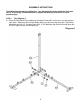
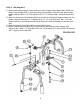
STEP 3 (See Diagram 3) A.) Slide two ∅ 2 ½” Rubber Bumpers (#58) onto two Chromed Guide Rods (#58). Insert the two Guide Rods into the holes on the Right Base Frame (#46). Slide the Selector Stem (#67) onto the two Guide Rods (#22). Slide the Selector Stem over the Selector Rod (#69). Secure the Selector Rod to the Selector Stem with two M10 x 1” Allen Bolts (#56). DO NOT install the plates yet. B.) Repeat the Procedure A above to install another set of Guide Rods. C.
DIAGRAM 3 7
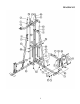
STEP 4 (See Diagram 4) A.) Attach the Front Press Base (#97) to the Right Base Frame (#46). Secure it with a 9 ¼” Front Press Axle (#60), two ∅ ¾” Washers (#6), and two M10 Aircraft Nuts (#5). B.) Attach the Front Press Frames (#63) to the Front Press Base. Secure it with four M10 x 2 ¾” Carriage Bolts (#17), ∅ ¾” Washers (#6), and M10 Aircraft Nuts (#5).
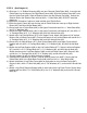
STEP 5 (See Diagram 5) A.) Attach the Butterfly Support Frame (#18) to the front of Right Vertical Beam (#21). Attach the Butter Pulley Support (#74) to the back of Right Vertical Beam. Align the holes. Secure them together with two M10 x 2 ¾” Carriage Bolts (#17), ∅ ¾” Washers (#6), and M10 Aircraft Nuts (#5). B.) Insert the Axle on the Left Butterfly (#20) into the hole on the Butterfly Support Frame from the bottom.
STEP 6 (See Diagram 6) A.) Attach the Vertical Press Frame (#78) to the Rear Vertical Beam (#50). Secure it with a M10 x 4 7/8” Vertical Press Axle (#81), two ∅ ¾” Washers (#6), and two M10 x 1” Allen Bolts (#56). B.) Place the Vertical Press Frame rest onto the ∅ 1 ½” Rubber Bumper (#83).
CABLE LOOP DIAGRAM 11
STEP 7 (Upper Cable Loop & Diagram 7) A.) Attach the 108” Upper Cable (#93) to the front opening on the Upper Frame (#8). Attach a Pulley (#79) to the opening. Secure it with one M10 x 2 ½” Allen Bolt (#10), two Pulley Bushings (#11), and one M10 Aircraft Nut (#5). Draw the Cable towards the back of the machine. Note: Make sure the Ball Stopper is underneath the frame. B.) Attach a Pulley to the bracket on the Upper Frame.
DIAGRAM 7 13
STEP 8 (See Butterfly Cable Loop & Diagram 8) A.) Attach the 106” Butterfly Cable (#95) to the slot on the back of Left Butterfly (#20). Draw the Cable through the slot then to the open left Swivel Pulley Bracket (#72). B.) Attach a Pulley (#79) to the bracket. Secure it with one M10 x 2” Allen Bolt (#98), two ∅ ¾” Washers (#6), and one M10 Aircraft Nut (#5). C.) Draw the Cable around the Pulley then downward. Install a Pulley to the Angled Double Floating Bracket (#51). Let the Bracket hanging for now. D.
DIAGRAM 8 15
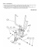
STEP 9 (See Front Press Cable Loop & Diagram 9) A.) Attach the 224” Front Press Cable (#94) to the lower opening on the Leg Developer (#40). B.) Attach a Pulley (#79) to the opening. Secure it with one M10 x 2 ½” Allen Bolt (#10), two Pulley Bushings (#11), and one M10 Aircraft Nut (#5). C.) Draw the Cable underneath the Pulley through the opening on the Right Seat Support (#49) to the open bracket on the Right Base Frame (#46). D.) Attach a Pulley to the bracket.
DIAGRAM 9 17
STEP 10 (See Leg Press Cable Loop & Diagram 10) A.) Attach one end of the 82” Leg Press Cable (#96) to the open slot on the back of the Leg Press Frame (#84). Secure it with one M10 x 2 ½” Allen Bolt (#10), two ∅ ¾” Washers (#6), and one M10 Aircraft Nut (#5). B.) Draw the Cable to the front opening on the Left Seat Support (#92). Attach a Pulley to the opening. Secure it with one M10 x 2 ½” Allen Bolt (#10), two Pulley Bushings (#11), and one M10 Aircraft Nut (#5). C.
DIAGRAM 10 19
STEP 11 (See Diagram 11) A.) Place a Seat Pad (#29) onto the Left Seat Support (#92). Secure it with two M8 x 2 1/8” Allen Bolts (#25) and ∅ 5/8” Washers (#24). B.) Attach a Backrest Board (#28) to the Left Vertical Beam (#77). Secure it with two M8 x 2 1/8” Allen Bolts (#25) and ∅ 5/8” Washers (#24). C.) Attach the Leg Press Plate (#76) onto the Leg Press Frame (#84). Secure it with a L-shaped Pin (#75).
STEP 12 (See Diagram 12) A.) Place a Seat Pad (#29) onto the Right Seat Support (#49). Secure it with two M8 x 2 1/8” Allen Bolts (#25) and ∅ 5/8” Washers (#24). B.) Attach a Backrest Board (#28) to the Right Vertical Beam (#21). Secure it with two M8 x 2 1/8” Allen Bolts (#25) and ∅ 5/8” Washers (#24). C.) Insert two Foam Roll Tubes (#36) halfway through the holes on the Right Seat Support (#49) and Leg Developer (#40). Push four Foam Rolls (#33) onto the Tubes from both sides.
STEP 13 (See Diagram 13) A.) Securely tighten all the nuts and bolts previously installed. B.) Before putting the Weight Plates on, now move the machine to the corner of the room or place where you will use the machine. C.) Lift up the Selector Rod and install one stack of 19 Weight Plates (#66). To install the plates, hold the plate at an angle and place between the two Guide Rods then drop it down. Make sure the grooves on the plastic covers all face up. All the Plates should interlock with each other.
PARTS LIST KEY NO.
WEIGHT RESISTANCE CHART WEIGHT PLATE Station 1 2 3 4 5 6 7 8 9 Low Pulley 35 45 55 65 75 85 95 105 115 Lat Pull 20 30 40 50 60 70 80 90 100 Butterfly 10 17 24 31 38 45 52 59 66 Leg Press 20 30 40 50 60 70 80 90 100 Front Press 40 50 60 70 80 90 100 110 120 Vertical Press 20 30 35 40 45 50 60 70 80 WEIGHT PLATE Station 10 11 12 13 14 15 16 17 18 19 Low Pulley 125 135 145 155 165 175 185 195 205 215 Lat Pull 110 120 130 140 15
24 IMPEX INC. LIMITED WARRANTY IMPEX Inc. ("IMPEX") warrants this product to be free from defects in workmanship and material, under normal use and service conditions, for a period of two years on the Frame from the date of purchase. This warranty extends only to the original purchaser. IMPEX's obligation under this Warranty is limited to replacing or repairing, at IMPEX's option. All returns must be pre-authorized by IMPEX.
25