
Owner's Manual


ASSEMBLY INSTRUCTION
Tools Required Assembling the Machine: One Adjustable Wrench and Allen
Wrench.
NOTE: It is strongly recommended this machine be assembled by two or more
people to avoid possible injury.
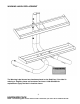
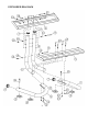
STEP 1 (See Diagram 1)
A.) Attach the Left Stabilizer (#3) to the Left Upright Beam (#4). Attach the Right
Stabilizer (#1) to the Right Upright Beam (#2). Place the Lower Dumbbell Rack (#5)
onto the two Stabilizers and Upright Beams. Align the holes and secure them with
four M10 x 3” Carriage Bolts (#12), ¾” Washers (#14), and M10 Aircraft Nuts
(#13). Do not tighten all the Nuts and Bolts yet.
B.) Slide the Upper Dumbbell Rack (#6) onto both Upright Beams. Align the holes on
the bracket to the two middle holes on the Upright Beams. Secure them together
with two M10 x 5 3/8” Carriage Bolts (#11), Ø ¾” Washers (#14), and M10 Aircraft
Nuts (#13). Do not tighten all the Nuts and Bolts yet.
C.) Secure the two Upright Beams with two M10 x 5 1/8” Allen Bolts (#9), four Ø ¾”
Washers (#14), and two M10 Aircraft Nuts (#13) to the top and lower holes on the
Upright Beams. Securely tighten all Nuts and Bolts installed.
D.) Set the rack on a flat surface. If the rack is un-even on the floor, use the two M10 x
3 1/8” Allen Bolts (#10) located on the bases to adjust the height of the rack. Turn
the Bolt clockwise to rack up the rack and turn the bolt counter-clockwise to lower
the rack.
5