NOTE: Please read all instructions carefully before using this product Table of Content Safety Notice Hardware Identifier Assembly Instruction Exploded Diagram EVERLAST COMBO BENCH W/ LAT BAR EVE-725 Parts List Warranty Ordering Parts Model EVE-725 Retain This Manual for Reference 07-06-05 OWNER'S MANUAL Made under license from trademark owner Everlast Worldwide Inc., New York. IMPEX INC. 14777 Don Julian Rd., City of Industry, CA 91746 Tel: (800) 999-8899 Fax (626) 961-9966 www.impex-fitness.
TABLE OF CONTENT BEFORE YOU BEGIN...............................................................................................1 IMPORTANT SAFETY NOTICE................................................................................2 HARDWARE IDENTIFIER.........................................................................................4 ASSEMBLY INSTRUCTIONS....................................................................................5 EXPLODED DIAGRAM............................................
IMPORTANT SAFETY NOTICE PRECAUTIONS This exercise machine is built for optimum safety. However, certain precautions apply whenever you operate a piece of exercise equipment. Be sure to read the entire manual before you assemble or operate your machine. In particular, note the following safety precautions: 1. Keep children and pets away from the machine at all times. DO NOT leave children unattended in the same room with the machine. 2. Only one person at a time should use the machine. 3.
WARNING LABEL REPLACEMENT The Warning Label shown here has been placed on the Cross Brace. If the label is missing or illegible, please call customer service at 1-800-999-8899 for replacement. Apply the label in location shown.
4
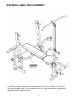
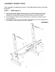
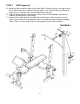
ASSEMBLY INSTRUCTION Tools required assembling the machine: Two Adjustable Wrenches and Allen Wrenches STEP 1 (SEE Diagram 1) A.) Connect the two Rear Upright Beams (#1) by a Cross Brace (#59) in the Mid-span. Secure them with two M10 x 2 3/8” Hex Bolts (#2), four ∅ ¾” Washers (#3), one Bracket (#7), and two M10 Aircraft Nuts (#4) on each end of the Cross Brace. B.) Insert the Backrest Adjustment Bar (#10) through a selected hole to obtain desired incline of Backrest. C.
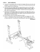
STEP 2 (SEE DIAGRAM 2) A.) Connect the Front Stabilizer (#42) to the Main Seat Support (#52) and secure them with two M10 x ¾” Hex Bolts (#46), four ∅ ¾” Washers (#3), and two M10 Aircraft Nuts (#4). DO NOT tighten the nuts and bolts yet. B.) Connect the Main Seat Support (#52) to the open bracket on the Cross Brace (#59). Secure the rear hole on the bracket with one M10 x 2 3/8” Bolt (#2), two ∅ ¾” Washers (#3), and one M10 Aircraft Nut (#4). Secure the other hole with a 3” Lock Pin (#58).
STEP 3 (SEE DIAGRAM 3) A.) Attach a ∅ ¾” Washer (#3) onto a M10 x 6 ¼” Hex Bolt (#54). Insert the Bolt through the Butterfly (#17). Place a M10 Regular Nut (#57) onto the Bolt. Then insert the Bolt through the hole on the Rear Upright Beam (#1). Secure the Bolt with a Lock Knob (#8) behind the Upright Beam. Repeat the same step to install the other Butterfly. B.) Attach the Right Butterfly Handle (#56) to the Right Butterfly (#17).
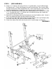
STEP 4 (SEE DIAGRAM 4) A.) Attach the hole-side of the Backrest Supports (#60) onto both ends of the Pivot on the Main Seat Support (#52). The other side rest against the Backrest Adjustment Bar (#10). B.) Place the Backrest Board (#18) onto the Backrest Supports (#60). Secure it with four M6 x 1 3/8” Hex Bolts (#50) and ∅ ½” Washers (#51). C.) Place Seat (#19) onto the bracket on the Main Seat Support (#52). Align the holes and secure the Seat with four M6 x 1 3/8” Hex Bolts (#50) and ∅ ½” Washers (#51).
STEP 5 (SEE Diagram 5) A.) Attach the ball end of the Cable to the Pulley (#28). Place the Pulley in the open slot on the Lat Bar Frame (#31). Secure it with one M10 x 2 1/8” Hex Bolt (#32), two Bushings (#29), two ∅ ¾” Washers (#3), and one M10 Aircraft Nut (#4). B.) Slide the Weight Holder (#33) onto the Lat Bar Frame from the bottom. Connect the Cable to the Holder with a Hook (#26). C.) Connect the Lat Bar (#25) to the Cable with a Hook (#26).
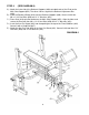
STEP 6 (SEE Diagram 6) A.) To store the bench in a vertical position, remove the Arm Curl and the Lat Bar Frame from the bench and place them onto the storage posts on the Rear Upright Beams. B.) Pull out the 3” Lock Pin (#58) on the Main Seat Support to fold up the bench. Make sure to re-insert the Lock Pin on the bracket to secure the vertical position.
11
PARTS LIST KEY NO.
IMPEX INC. LIMITED WARRANTY IMPEX Inc. ("IMPEX") warrants this product to be free from defects in workmanship and material, under normal use and service conditions, for a period of two years on the Frame from the date of purchase. This warranty extends only to the original purchaser. IMPEX's obligation under this Warranty is limited to replacing or repairing, at IMPEX's option. All returns must be pre-authorized by IMPEX.