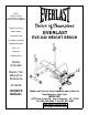
NOTE: Please read all instructions carefully before using this product Table of Contents Safety Notice Hardware Pack Assembly Instruction EVERLAST EVE-840 WEIGHT BENCH Exploded Diagram Parts List Warranty Ordering Parts Model EVE-840 Retain This Manual for Reference 07/06/05 OWNER'S MANUAL Made under license from trademark owner Everlast Worldwide Inc., New York. IMPEX INC. 14777 Don Julian Rd., City of Industry, CA 91746 Tel: (800) 999-8899 Fax (626) 961-9966 www.impex-fitness.com info@impex-fitness.
TABLE OF CONTENTS BEFORE YOU BEGIN...................................................................................... IMPORTANT SAFETY NOTICE....................................................................... HARDWARE PACK………............................................................................... ASSEMBLY INSTRUCTIONS........................................................................... EXPLODED DIAGRAM....................................................................................
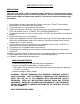
IMPORTANT SAFETY NOTICE PRECAUTIONS This exercise machine is built for optimum safety. However, certain precautions apply whenever you operate a piece of exercise equipment. Be sure to read the entire manual before you assemble or operate your machine. In particular, note the following safety precautions: 1. Keep children and pets away from the machine at all times. DO NOT leave children unattended in the same room with the machine. 2. Only one person at a time should use the machine. 3.
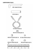
WARNING LABEL REPLACEMENT The Warning Label shown here has been placed on the Front Stabilizer. If the label is missing or illegible, please call customer service at 1-800-999-8899 for replacement. Apply the label in location shown.
HARDWARE PACK 4
HARDWARE PACK 5
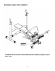
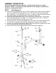
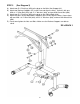
ASSEMBLY INSTRUCTION Tools Required Assembling the Machine: Two Adjustable Wrenches and Allen Wrenches. NOTE: It is strongly recommended two or more people assembling this machine to avoid possible injury. STEP 1 (See Diagram 1) A.) Connect the Right Upright Beam (#3) to a Rear Stabilizer (#14). Make sure this Stabilizer does not have Roller End Cap (#59) on its ends. Secure them with one Bent Bracket (#17), two M10x3 ¾” Carriage Bolts (#47), two ∅ ¾” Washers (#48) and two M10 Aircraft Nuts (#50).
STEP 2 (See Diagram 2) A.) Connect the Main Seat Support (#1) to a Rear Stabilizer (#14). Make sure this Stabilizer has two Roller End Caps (#59). Secure them with one Bent Bracket (#17), two M10 x 3 ¾” Carriage Bolts (#47), two ∅ ¾” Washers (#48), and two M10 Aircraft Nuts (#50). B.) Connect the Main Seat Support (#1) to the Front Stabilizer (#5). Secure them with one Bent Bracket (#17), two M10 x 3 ¾” Carriage Bolts (#47), two ∅ ¾” Washers (#48), and two M10 Aircraft Nuts (#50). C.
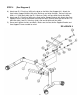
STEP 3 (See Diagram 3) A.) Attach two Ø ¾” Bushings (#54) to the pivot on the Main Seat Support (#1). B.) Attach two Backrest Supports (#7) to the Pivot and align the holes. Secure it with one M10 x 6 ¼” Allen Bolt (#39), two ∅ ¾” Washers (#48), and one M10 Aircraft Nut (#50). C.) Attach two Ø ¾” Bushings (#54) to the pivot on the Sliding Block (#10). D.) Attach the holes on the two Backrest Supports to the Pivot. Align the holes.
STEP 4 (See Diagram 4) A.) Attach two Ø ¾” Bushings (#54) to the pivot on the Main Seat Support (#1). Attach the Seat Incline Support Bracket (#8) to the Bushings and align the holes. Secure it with one M10 x 4 ½” Allen Bolt (#40), two Ø ¾” Washers (#48), and one M10 Aircraft Nut (#50). B.) Attach two Ø ¾” Bushings (#54) to the Seat Incline Support Bracket (#8). Attach two Seat Support Frames (#6) to the Bracket and align the holes.
STEP 5 (See Diagram 5) A.) Attach four Ø ¾” Bushings (#54) to the two Seat Support Frames (#6). Attach another four ∅3/4” Bushings (#54) to the two Backrest Supports (#7). B.) Attach a Backrest Support (#7) to a Seat Support Frame (#6). Please note that the Backrest Support should be on the inside of the Seat Support Frame. Secure them with one M10 x 2 3/8” Allen Bolt (#42) and M10 Aircraft Nut (#50). C.) Repeat the same procedure to install the other side. D.) Do not over tighten the Nuts and Bolts.
STEP 6 (See Diagram 6) A.) Place the Seat (#22) onto the Seat Support Frame (#6). Secure it with four M8 x 2” Allen Bolts (#44) and Ø5/8” Washers (#49). B.) Place the Backrest Board (#23) onto the Backrest Supports (#7). Secure it with four M8 x 2” Allen Bolts (#44) and Ø5/8” Washers (#49).
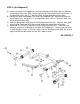
STEP 7 (See Diagram 7) A.) Attach the Leg Developer (#4) to the bracket on the top of Main Seat Support (#1). Secure it with one Axle (#16), two M10x ¾” Allen Bolts (#43), and ؾ” Washers (#48). B.) Insert one Foam Roll Tube (#15) halfway through the hole on the Main Seat Support. Insert two Foam Roll Tubes halfway through the holes on the Leg Developer. Push six Foam Rolls (#18) onto the Tubes from both ends. Plug six Foam Roll End Caps (#31) into the Ends. C.
13
PARTS LIST KEY NO.
IMPEX INC. LIMITED WARRANTY IMPEX Inc. ("IMPEX") warrants this product to be free from defects in workmanship and material, under normal use and service conditions, for a period of two years on the Frame from the date of purchase. This warranty extends only to the original purchaser. IMPEX's obligation under this Warranty is limited to replacing or repairing, at IMPEX's option. All returns must be pre-authorized by IMPEX.