NOTE: Please read all instructions carefully before using this product Table of Contents Safety Notice Hardware Pack Assembly Instruction Parts List MARCY CORNER GYM MWM-8900 Resistance Chart Warranty Ordering Parts Model MWM-8900 Retain This Manual for Reference 08-12-05 OWNER'S MANUAL IMPEX INC. 14777 DON JULIAN RD., CITY OF INDUSTRY, CA 91746 Tel: (800) 999-8899 Fax: (626) 961-9966 www.impex-fitness.com info@impex-fitness.
TABLE OF CONTENTS BEFORE YOU BEGIN...................................................................................... IMPORTANT SAFETY NOTICES..................................................................... HARDWARE PACK……….....…....................................................................... ASSEMBLY INSTRUCTIONS...............................................................….......... PARTS LIST…………………………………………………………….……….……. RESISTANCE CHART………………………………………………………………. WARRANTY...............
IMPORTANT SAFETY NOTICE PRECAUTIONS This exercise machine is built for optimum safety. However, certain precautions apply whenever you operate a piece of exercise equipment. Be sure to read the entire manual before you assemble or operate your machine. In particular, note the following safety precautions: 1. Keep children and pets away from the machine at all times. DO NOT leave children unattended in the same room with the machine. 2. Only one person at a time should use the same station. 3.
WARNING LABEL REPLACEMENT The warning labels shown here have been placed on the Rear Base and Upper Frame. If the labels are missing or illegible, please call customer service at 1-800-888-8899 for replacements. Apply the labels in location shown.
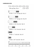
HARDWARE PACK 4
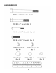
HARDWARE PACK 5
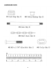
HARDWARE PACK 6
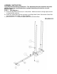
ASSEMBLY INSTRUCTION Tools Required Assembling the Machine: Two Adjustable Wrenches and Allen Wrenches NOTE: It is strongly recommended two or people assembling this machine to avoid possible injury. STEP 1 (See Diagram 1) A.) Place the Right Base Frame (#1) on a flat surface. Make sure there is enough space around to assemble the machine. B.) Insert four Guide Rods (#4) into the holes on the Right Base Frame. Secure each Guide Rod from the bottom with a M10 x 1” Allen Bolt (#94). C.
STEP 2 (See Diagram 2) A.) Attach the Left Base and the Rear Base Frame (#2 & #3) to the Right Base Frame (#1). B.) Align the holes and secure them with two M10 x 2 ½” Carriage Bolts (#98), ∅ ¾” Washers (#21), and M10 Aircraft Nuts (#18).
STEP 3 (See Diagram 3) A.) Slide fourteen Weight Plates (#54) onto the rear set of Guide Rods (#4). Make sure the groove on the plates all face toward the front of the machine. B.) Insert a Selector Rod (#53) into the center holes. Slide a Selector Stem (#34) onto the two Guide Rods. Slide a Ø 1 ¾” Rubber Bumper (#34) onto the Selector Rod. C.) Repeat procedures A & B above to install the other fourteen Weight Plates onto the front two Guide Rods. Make sure the grooves face the back of the machine.
STEP 4 (See Diagram 4) A.) Do not tighten all Nuts and Bolts in this step until instructed to do so. B.) Attach the Right Vertical Frame (#5) to the Right Base Frame (#1). Secure it with two M10 x 2 ½” Carriage Bolts (#98), Ø ¾” Washers (#21), and M10 Aircraft Nuts (#18). C.) Attach the Left Vertical Frame (#6) to the Left Base Frame (#2). Secure it with one M10 x 2 ½” Carriage Bolt (#98), Ø ¾” Washer (#21), and M10 Aircraft Nut (#18). D.) Attach the Rear Vertical Frame (#7) to the Rear Base Frame (#3).
STEP 5 (See Diagram 5) A.) Do not tighten all Nuts and Bolts in this step until instructed to do so. B.) Place the Upper Frame (#8) onto the Right Vertical Frame (#5) and two Guide Rods (#4). Secure the Upper Frame to the Right Vertical Frame with two M10 x 2 ½” Carriage Bolts (#98), one 4 3/8” x 1 ¾” Bracket (#84), two Ø ¾” Washers (#21), and two M10 Aircraft Nuts (#18). C.) Secure the Upper Frame to the two Guide Rods with two M10 x 1” Allen Bolts (#94) and Ø ¾” Washers (#21). D.
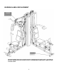
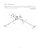
STEP 6 (See Diagram 6) A.) Securely tighten all Nuts and Bolts previously installed. B.) Attach the Right Seat Support (#10) to the Right Base Frame (#1). Secure it with one M10 x 2 ½” Carriage Bolt (#98), Ø ¾” Washer (#21), and M10 Aircraft Nut (#18). C.) Attach the Right Seat Support (#10) to the Right Vertical Frame (#5). Secure it with two M10 x 2 ½” Carriage Bolts (#98), one 4 3/8” x 1 ¾” Bracket (#84), two Ø ¾” Washers (#21), and two M10 Aircraft Nuts (#18). D.
DIAGRAM 6 13
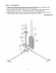
STEP 7 (See Diagram 7) A.) Attach the Left Seat Support (#11) to the Left Base Frame (#2). Secure it with one M10 x 2 ½” Carriage Bolt (#98), Ø ¾” Washer (#21), and M10 Aircraft Nut (#18). B.) Attach the Left Seat Support (#11) to the Left Vertical Frame (#6). Secure it with two M10 x 2 ½” Carriage Bolts (#98), one 4 3/8” x 1 ¾” Bracket (#84), two Ø ¾” Washers (#21), and two M10 Aircraft Nuts (#18). C.) Attach the Leg Press Frame (#25) to the bracket on the Left Base Frame.
STEP 8 (See Diagram 8) A.) Insert the axle on the Right Butterfly (#15) through a Butterfly Adjustment Frame (#50) into the Butterfly Support Frame (#12). Secure it with one M10 x 5/8” Allen Bolt (#93), Ø ¾” Washer (#21), and Lock Ring (#33). B.) Thread a T-shaped Pull Pin (#66) into the hole on the Right Butterfly from the bottom. Use the Pin to adjust the Butterfly position. C.) Repeat the same procedures A & B above to install the Left Butterfly (#14). D.
STEP 9 (See Diagram 9) A.) Attach the Vertical Press Base (#23) to the pivot on the Rear Vertical Frame (#7). Secure it with one Axle (#59), two Ø ¾” Washers (#21), and two M10 Aircraft Nuts (#18). B.) Attach one Vertical Press Arm (#24) to the Vertical Press Base. Secure it with two M10 x 2 ½” Carriage Bolts (#98), Ø ¾” Washers (#21), and M10 Aircraft Nuts (#18). C.) Repeat the same procedure to install the other Vertical Press Arm.
CABLE LOOP DIAGRAM 17
STEP 10 (See Cable Loop Diagram & Diagram 10) A.) Attach the 102” Upper Cable (#36) to the front opening on the Upper Frame (#8). Attach a Pulley (#64) to the opening. Secure it with one M10 x 2 3/8” Allen Bolt (#96), two Pulley Bushings (#63), and one M10 Aircraft Nut (#18). Draw the Cable towards the back of the machine. Note: Make sure the Ball Stopper is underneath the frame. B.) Attach a Pulley to the opening on the Upper Frame.
DIAGRAM 10 19
STEP 11 (See Cable Loop Diagram & Diagram 11) A.) Clip one end of the 76” Butterfly Cable (#37) to the slot on the Left Butterfly Adjustment Frame (#50). Draw the Cable through the slot then to the open Swivel Pulley Bracket (#49). B.) Attach a Pulley (#64) to the bracket. Secure it with one M10 x 1 ¾” Allen Bolt (#95), two ∅ ¾” Washers (#21), and one M10 Aircraft Nut (#18). C.) Draw the Cable around the Pulley then downward. Install a Pulley to an Angled Floating Pulley Bracket (#31).
STEP 12 (See Cable Loop Diagram & Diagram 12) A.) Attach the 146” Lower Cable (#35) to the lower opening on the Leg Developer (#26). Attach a Pulley (#64) to the opening. Secure it with one M10 x 2 3/8” Allen Bolt (#96), two Pulley Bushings (#63), and one M10 Aircraft Nut (#18). B.) Draw the Cable underneath the Pulley to the opening on the bottom of Right Seat Support (#10).
DIAGRAM 12 22
STEP 13 (See Diagram 13) A.) Attach the 49” Front Press Cable (#38) to the small opening on the Right Vertical Frame (#5). Secure the head of the Cable to the small opening with one M10 x 2 3/8” Allen Bolt (#96), two Ø ¾” Washers (#21), and one M10 Aircraft Nut (#18). B.) Draw the Cable to the open bracket on the Front Press Base (#29). Install a Small Pulley (#65) to the bracket. C.
STEP 14 (See Diagram 14) A.) Attach a Short Chain (#88) to the open bracket on the Rear Vertical Frame (#7). Secure it with one M10 x 1” Allen Bolt (#94), two Ø ¾” Washers (#21), and one M10 Aircraft Nut (#18). B.) Connect the 94” Vertical Press Cable (#39) to the Short Chain with a C-clip (#89). C.) Install a Pulley to an Angled Floating Pulley Bracket (#31). D.) Draw the Cable around the Pulley then upward to the first open bracket on the Top Socket Assemble (#9). E.
DIAGRAM 14 25
STEP 15 (See Diagram 15) A.) Attach the 216” Leg Press Cable (#40) to the bracket on the back of Leg Press Frame (#25). Secure it with one M10 x 1” Allen Bolt (#94), two Ø ¾” Washers (#21), and one M10 Aircraft Nut (#18). Draw the Cable to the open bracket on the Left Seat Support (#11). Install a Pulley to the bracket. Draw the Cable around the Pulley then back to the open bracket on the Leg Press Frame. Install another Pulley. B.
STEP 16 (See Diagram 16) A.) Place a Seat Pad (#42) onto the Seat Incline Adjustment Frame (#27). Secure it with two M8 x 1 5/8” Allen Bolts (#102) and ∅ 5/8” Washers (#20). Insert the Frame into the opening on the Left Seat Support (#11). Use a Lock Knob (#68) to secure the Seat at selected height. B.) Insert two Foam Tubes (#13) halfway through the holes on the Right Seat Support (#10) and the Leg Developer (#26). Push four Vinyl Foam Rolls (#58) onto the Tubes from both ends.
STEP 17 (See Diagram 17) A.) Attach the Backrest Board (#41) to the Right & Left Vertical Frames (#5 & #6). Secure each Board with two M8 x 2 ½” Allen Bolts (#101) and Ø 5/8” Washers (#20). B.) Place the Seat (#42) onto the Right Seat Support (#10). Secure it with two M8 x 2 ½” Allen Bolts (#101) and Ø 5/8” Washers (#20). C.) Attach four Arm Pads (#43) to the Right and Left Butterfly (#15 & #14). Secure each Arm Pad with two M8 x 2 ½” Allen Bolts (#101) and Ø 5/8” Washers (#20). D.
PARTS LIST KEY NO.
MWM-8900 WEIGHT RESISTANCE CHART WEIGHT PLATE Station 1 2 3 4 5 6 7 Low Pulley 35 45 55 65 75 85 95 Lat Pull 15 25 35 45 55 65 75 Butterfly 10 17 24 31 38 45 52 Leg Press 30 50 70 90 110 130 150 Front Press 35 50 65 80 95 110 125 Vertical Press 30 43 56 69 82 95 108 WEIGHT PLATE Station 8 9 10 11 12 13 14 Low Pulley 105 115 125 135 145 155 165 Lat Pull 85 95 105 115 125 135 145 Butterfly 73 80 87 94 101 108 115 Leg Press
IMPEX INC. LIMITED WARRANTY IMPEX Inc. ("IMPEX") warrants this product to be free from defects in workmanship and material, under normal use and service conditions, for a period of two years on the Frame from the date of purchase. This warranty extends only to the original purchaser. IMPEX's obligation under this Warranty is limited to replacing or repairing, at IMPEX's option. All returns must be pre-authorized by IMPEX.